




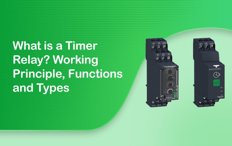
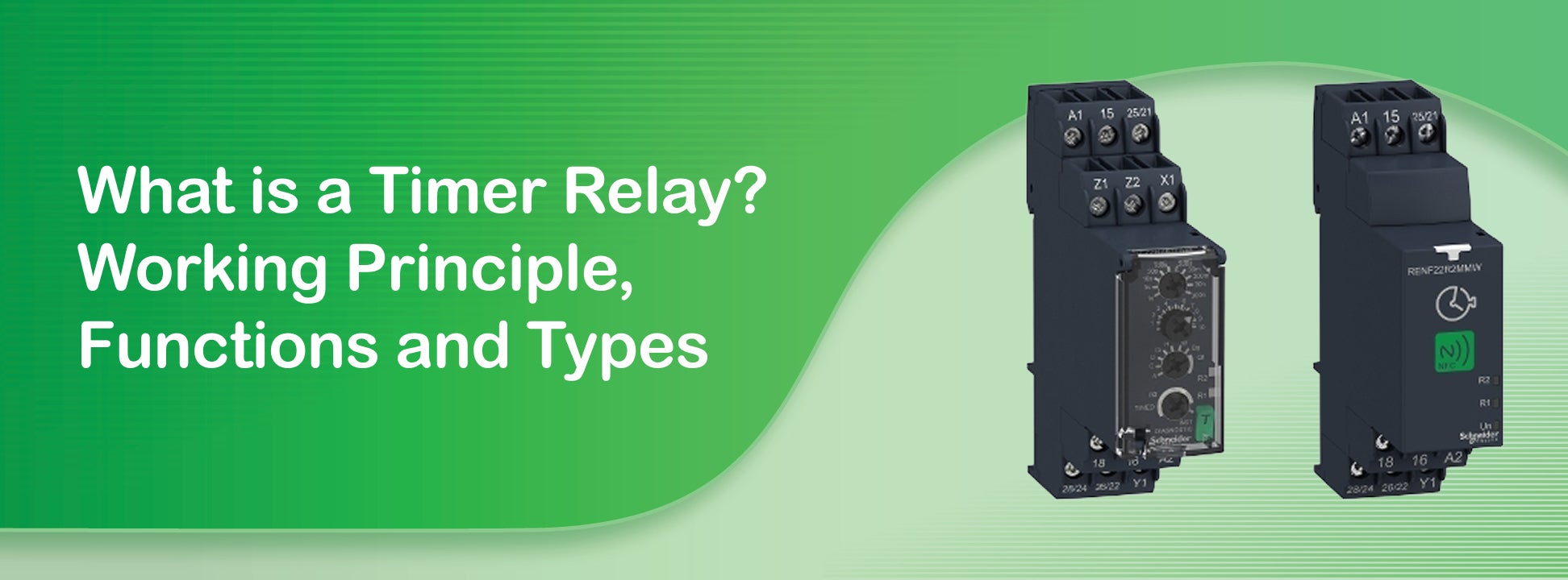
What is a Timer Relay? Working Principle, Functions and Types
Summary
Many control panels need a pause before a load starts or stops. A timer relay provides that pause with accuracy. This guide explains what is timer relay hardware and how does timer relay work through an internal clock circuit and an output contact. It covers the timer relay working principle, each major timer relay function and the types of timer relays used in industry. It also shows how a timer relay circuit diagram links the coil, supply and load in a simple control circuit.
Key Takeaways
- A timer relay switches output contacts after a preset delay, supporting accurate timing and automated control in industrial applications.
- Common timer relay functions include on-delay, off-delay, interval, flasher, and star-delta timing for different operational requirements.
- Electronic, pneumatic, motor-driven, and thermal timer relays differ in accuracy, construction, timing range, and suitability.
- Timer relay terminals A1 and A2 provide the supply connection, while terminals 15, 16, and 18 control output switching.
- Timer relays help sequence motor starting, extend cooling fan operation, control warning lights, and automate pumps and conveyors.
- Correct supply voltage, contact ratings, wiring connections, and contactor selection are essential for safe, reliable timer relay operation.
Introduction
Certain machines have to wait before carrying out an action. It is not advisable for a compressor to restart immediately after it has stopped. A fan should continue to run after a heater has switched off. A motor should not change from star to delta connection all at once. Each of these operations requires an exact delay, and a person cannot do this in a reliable manner. Instead, a small device located within the control panel carries out the task. This device keeps track of time and then alters the state of its output. Consider the example of a staircase light which switches off sixty seconds after the button has been pressed. The same principle applies to pumps, lifts, conveyors and heating plants. The sections that follow explain the components, the operating steps and the main types.
What is Timer Relay
A timer relay is an auxiliary control device which, after a predetermined period of time, delays the opening or closing of its output contacts. It takes in a supply signal, counts the delay using an internal timing circuit, and then causes a changeover contact to move. The delay can be set using a rotary dial, DIP switches or a digital display and the accuracy is generally within 1 to 5 per cent of the set value. In practice, the device does not carry the main load current but instead gives a signal to a larger switching device, for example a contactor relay, which is then what operates the motor or heater. A contactor relay is commonly used when the controlled load requires higher current. This ensures that the timing circuit remains small and reliable.
Timer Relay Components
In a timer relay, several components share the duties. One part keeps track of the time, another switches the output, and a third one sets the delay and displays the result. Knowing what these parts do makes it much easier to connect the circuit and carry out fault finding, since each component has a definite role within it. The three main types are described below.
Timing Circuit
The delay is measured by the timing circuit; in electronic circuits an RC network is used, consisting of a capacitor which charges through a resistor until the threshold voltage is reached. Digital models employ a microcontroller together with a crystal oscillator, thereby achieving greater accuracy and repeatability. Pneumatic types make use of an air bellows with an adjustable needle valve. The longer the delay, the greater the value of the resistance or capacitance, so the dial is used to alter that value.
Output Relay and Contacts
The output section consists of an electromagnetic relay having a coil and a number of contacts. Terminal 15 is the common terminal, terminal 16 is the normally closed contact and terminal 18 is the normally open contact. The silver alloy contacts are rated at 5 A to 16 A for a 250 V AC supply. In some models solid-state outputs are used, these having no moving parts and being suitable for very frequent switching.
Power Supply, Dial and Indicators
The supply, for example 24 V DC or 230 V AC, is connected to the coil terminals A1 and A2. Those that are multi-voltage types include a range from 12 V to 240 V in a single housing. The delay and the range—going from seconds to hours—are set by means of a dial in front or a digital display. LED indicators display both the supply and output conditions; a green light usually means that power is on and a yellow light indicates that the relay has been energised.
Timer Relay Function
The different timer relay functions show how the output follows the input in terms of time, and choosing the appropriate one determines whether the machine starts late, stops late or operates for a fixed period. Four of these functions are most commonly used in panel work.
On-Delay Function
When using on-delay timing, the output alters after the set period has elapsed since the power is applied. If the power fails before the time period is up, the count is reset. This type of timing is suitable for sequential motor starting, in which a second conveyor is to start 10 seconds after the first one. It also delays the operation of a pump until the pressure has built up. On-delay is the most commonly found function on standard units.
Off-Delay Function
In the case of off-delay timing, the output turns on immediately and then remains on for the predetermined period once the trigger has been withdrawn. This type of timing is used with cooling fans that follow a heater or a furnace. The fan can continue to run for two minutes after the heater has switched off. Since most off-delay units require a separate trigger input, the power supply remains connected during the delay period.
Interval and Flasher Functions
With interval timing the output remains on for a fixed period and is then switched off, even though the input is still on; while with flasher timing the output alternates between on and off at a constant rate. Interval timing is suitable for door openers and dosing pumps, whereas flasher timing is appropriate for warning lamps and alarm horns. Both types use the same timing circuit but have different logic.
Star-Delta Function
A star-delta timer causes a motor to switch from a star to a delta connection after a predetermined time, this time usually being between 3 and 10 seconds; there is a short interval of about 50 milliseconds between the two contactors in order to prevent a short circuit. By starting in star connection the starting current is reduced to approximately one third of its direct value and this provides protection for both the supply and the motor winding.
How Does Timer Relay Work
The steps in operation are simple when you look at them in sequence: the supply comes, the clock counts, and then the contacts switch. The working principle of the timer relay is based on this sequence, and all the different functions adhere to the same pattern with only minor variations. This is the timer relay working principle in a typical control application. The entire thing can be clearly explained by referring to a brief sequence and a typical connection.
Working Sequence
The timing circuit is activated when the supply reaches A1 and A2; at this point the capacitor charges or the microcontroller counts the pulses. After the delay has occurred, the comparator causes the coil driver to be triggered and the output relay becomes energised. As a result, contact 15-18 closes while 15-16 opens. The load then begins to operate via the contactor. If the supply is switched off the circuit is reset within milliseconds and is ready for the next cycle.
Timer Relay Circuit Diagram
The diagram of a simple timer relay circuit includes a start button, the timer coil and the contactor coil in the control circuit which is operated at 230 V AC. The stop button is placed in series with the power supply. When the start button is pressed, A1 and A2 get energised. Then, after the delay has occurred, contact 15-18 closes and supplies power to the contactor coil. A holding contact ensures that the circuit remains active. The main power wiring is kept separate from this control circuit.
Wiring and Connection Steps
When wiring a timer relay, connect the live wire to A1 and the neutral wire to A2, and then join terminals 15 and 18 in series with the contactor coil. For the control circuits, use wire that is 1.5 mm² in size and ensure that the terminals are tightened to the specified torque. The connection diagram for the timer relay shown on the housing label indicates the same arrangement. Refer to the timer relay wiring diagram and timer relay connection diagram before installation; the timer relay wiring diagram and timer relay connection diagram should match the terminal markings. Always switch off the power before carrying out the wiring, and first check the delay with no load applied.
Types of Timer Relays
Timer relays vary according to the way in which they measure time and the way in which they switch. The most suitable type will depend on the requirements concerning accuracy, the number of cycles, and the conditions of the working environment. The different types of timer relay are grouped by their construction as shown below.
Electronic Timer Relays
Electronic timers make use of an RC circuit or a microcontroller; they provide a wide range of settings, high accuracy and a compact size. A number of them have several functions incorporated in a single unit, these functions being chosen by means of a switch. The delay times vary from 0.1 seconds to 100 hours and the lifetime extends to 10 million operations when using a solid-state output. They are suitable for most modern control panels.
Pneumatic Timer Relays
Pneumatic timers are set by means of air flow passing through a needle valve. They are installed as additional blocks on a contactor. The time range is generally from 0.1 to 180 seconds. They do not require a power supply for the timing function, though their accuracy is only about 10 per cent. They are appropriate for simple and robust applications where electronics could be influenced by electrical noise.
Motor-Driven and Thermal Timer Relays
Motor-driven timers consist of a small synchronous motor and a cam which are used to measure time; they are capable of providing delays of several hours or even days and are frequently found in older equipment and in lighting control systems. Thermal timers make use of a bimetallic strip which heats up and bends in order to switch the contacts. Although they are inexpensive and durable, their accuracy is limited. Nowadays both types are less frequently used than electronic ones.
Conclusion
A timer relay can provide a controlled delay to a circuit and is used for protecting motors, for sequencing equipment and for saving energy. The choice of relay will depend on the required function, the supply voltage, the contact rating and the construction type. The system will remain safe if the wiring is done correctly together with a clear control circuit and an appropriate contactor. Schneider Electric eShop provides a wide variety of electrical products for timer relays, contactors, protection devices and other panel components.
FAQs
1. What is the difference between a timer relay and a time delay relay?
The names are used for the same device in most catalogues. Some makers use “time delay relay” for on-delay and off-delay units only.
2. How is delay accuracy rated?
Accuracy is stated as repeat accuracy, usually within 1 percent, and setting accuracy, within 5 percent. Temperature and supply changes may add small errors.
3. What causes a timer relay to fail?
Common causes are voltage spikes, worn contacts, overheating and wrong supply voltage. A suppressor across inductive loads extends contact life.
4. Can a timer relay be used with DC supply?
Yes. Many models accept 12 V, 24 V or 48 V DC. Check polarity at A1 and A2 before powering up.
5. How is a timer relay tested?
Apply the rated supply and measure continuity between terminals 15 and 18. The reading should change after the set delay.
Comments