



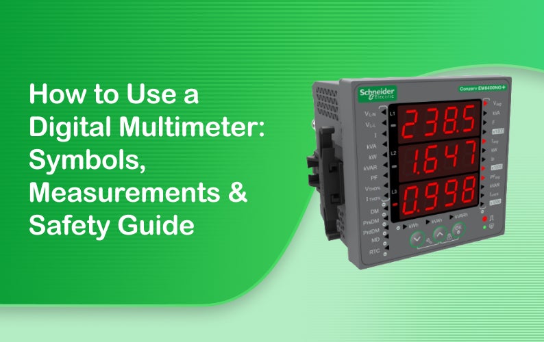
How to Use a Digital Multimeter: Symbols, Measurements & Safety Guide
Summary
Every panel builder, electrician, and electronics technician reaches for the same tool first. The digital multimeter. This multimeter guide covers how to use multimeter functions correctly. It explains what is a multimeter used for across residential and Industrial Automation settings, and breaks down multimeter symbols meaning so the rotary dial stops being a mystery. It also walks through how does a multimeter work internally, plus a full step-by-step measurement process for voltage, resistance, continuity, and current.
Key Takeaways
- A multimeter measures voltage, resistance, current, and continuity. All through one compact device.
- Voltage gets measured in parallel, across two points. Current gets measured in series, breaking the circuit and routing it through the meter directly. Mixing these two up is the single most common mistake. It usually ends with a blown fuse.
- Continuity testing always happens with power off, never live.
- Auto-ranging models pick the correct decimal placement automatically.
- Manual-range meters need a selected range first. Industrial technicians lean on multimeters constantly.
- Checking 24V DC PLC signals, sensor loop currents, and ground bonding, often dozens of times in a single shift.
Introduction
Walk into any industrial control room, and one tool sits in nearly every technician's pocket. The digital multimeter. Panel builders reach for it first. So do electricians, and electronics technicians troubleshooting a stubborn circuit board. It has earned that trust for a reason. Digital multimeter how to use principles start with three things. The central rotary dial, the probe ports, and the display itself, which shows readings across several different measurement modes. None of it is complicated once the basics click into place. Inside Industrial Automation environments specifically, a multimeter does real, constant work. Troubleshooting 24V DC PLC input and output voltages. Testing solenoid coils for continuity. Verifying sensor loop currents in the standard 4 to 20mA range. And checking ground bonding to confirm a safe, unbroken path to earth.
Multimeter Symbols Meaning Cheat Sheet
The rotary dial on a digital multimeter looks intimidating at first glance. Packed with symbols that mean nothing to someone new to the tool. Each one, though, represents a specific measurement type. Learning them takes far less time than most people expect. Understanding multimeter symbols meaning correctly from the start prevents a surprisingly common mistake. Selecting the wrong mode and getting a reading that looks plausible but is actually meaningless. The table below covers the symbols encountered most often on a standard digital multimeter dial.
| Dial Symbol | Technical Measurement | Meaning & Application |
|---|---|---|
| Ṽ | AC Voltage | Measures alternating voltage in AC circuits, such as household outlets and electrical supply lines. |
| V̄ | DC Voltage | Measures direct voltage from batteries, DC power supplies and electronic circuits. |
| Ω | Resistance (Ohms) | Measures electrical resistance in resistors, heating elements and other circuit components. |
| ))) | Continuity Test | Checks whether a continuous, low-resistance electrical path exists, usually producing an audible beep. |
| Ã | AC Current | Measures alternating current flowing through an AC circuit. |
| Ā | DC Current | Measures direct current flowing through a DC circuit. |
| →| | Diode Test | Checks the forward voltage drop and condition of a semiconductor diode. |
How Does a Multimeter Work?
How does a multimeter work internally? The short answer involves a handful of input ports and an internal switching network. It routes current or voltage through different measurement circuits depending on the dial position. Two aspects matter most for practical use. Understanding what each port actually does. And knowing the difference between auto-ranging and manual-ranging designs.
The Ports Demystified
Most digital multimeters have three ports, and each serves a distinct purpose. The COM port is the universal ground reference, used for every single measurement without exception. The port labeled V, Ω, mA, with the continuity symbol alongside it, handles roughly 90% of everyday measurements. Voltage, resistance, continuity, and low current readings. A separate 10A or 20A fused port exists specifically for high-current measurements, bypassing the sensitive low-amperage internal shunt that protects the standard measurement circuitry from damage.
Auto-Ranging vs. Manual Ranging
Auto-ranging multimeters detect the approximate magnitude of whatever is being measured. They automatically select the correct decimal placement, showing a clean reading without any manual adjustment. Manual-ranging meters work differently. The technician has to select a fixed range beforehand, something like 200mV, 20V, or 200V, guessing reasonably close to the expected value. Auto-ranging costs a bit more but removes guesswork entirely. That is why most modern meters, industrial and consumer alike, now ship with this feature as standard.
Step-by-Step Measurement Guide
Learning how to use multimeter functions properly comes down to four core measurements. Each one with its own setup and its own risks if done incorrectly. Voltage, continuity, resistance, and current each demand a specific probe placement and dial setting. Getting any of them wrong can range from a meaningless reading to a genuinely dangerous short circuit.
Step 1: How to Measure Voltage (AC & DC)
Start by plugging the black probe into the COM port and the red probe into the VΩmA port. Turn the rotary dial to the DC voltage symbol for batteries and electronics, or the AC voltage symbol for wall outlets and mains circuits. Touch both probes in parallel across the two points being tested. Never break the circuit to do so. Read the displayed value directly. In DC mode, a negative sign simply means the probes are reversed relative to actual polarity. Not an error.
Step 2: How to Test Continuity (Testing Cables & Switches)
Before anything else here, power to the circuit must be completely off, and any capacitors discharged fully. Set the dial to the continuity symbol. Touch the two probes together first, confirming the meter emits a continuous beep. That verifies the meter itself is functioning correctly. Then touch the probes across the wire, fuse, or switch contact being tested. A beep confirms a closed circuit, essentially zero ohms. No beep, or a display reading "OL," indicates an open circuit, a blown fuse, or a broken wire somewhere in the path.
Step 3: How to Measure Resistance (Ω)
Resistance measurement requires the circuit to be completely powered down first. No exceptions. Set the dial to the ohms symbol. Place the probes in parallel across the resistor or heating element under test. Try to isolate the component from the rest of the circuit if possible, since parallel paths can skew the reading. Compare the displayed value against manufacturer specifications for that component. A reading of "OL" here indicates infinite resistance. Meaning an open circuit somewhere in the component itself.
Step 4: How to Measure Current (Amperes, AC & DC)
Current measurement works differently from every other mode, and getting this step wrong is the most common way to damage a multimeter. The meter has to be placed in series, not parallel. That means the circuit itself gets physically broken and the meter inserted into that gap. For currents above 400mA, the red probe needs to move into the 10A port instead of the standard one. Set the dial to AC or DC current mode as appropriate, restore power, take the reading. Then immediately move the red probe back to the voltage port once finished.
Critical Multimeter Safety Rules
A multimeter is a genuinely safe tool when used correctly. A genuinely dangerous one when it is not. Most serious incidents trace back to a handful of predictable, preventable mistakes. The rules below cover the ones that matter most, particularly in industrial settings where voltage and current levels run considerably higher than household electronics.
Never Measure Current in Parallel
The single most common cause of a blown fuse, or worse, a dangerous short circuit, is leaving the red probe in a current port while attempting a voltage measurement across a live source. Current ports carry near-zero internal resistance by design. Connecting them across a voltage source creates an effective short circuit instantly. Always double-check probe placement matches the selected dial mode before touching anything live. Every single time.
Respect Voltage and Current Ratings
Every multimeter carries a maximum rated voltage and current, clearly marked on the device itself or in its manual. Exceeding these ratings, even briefly, risks internal component failure, arc flash, or physical injury to the person holding the probes. Industrial environments often involve voltages well beyond typical household levels. Confirming a meter's category rating, CAT II, CAT III, or CAT IV, against the actual circuit being tested is a step that should never get skipped.
De-Energize Before Resistance or Continuity Testing
Resistance and continuity measurements assume the circuit is completely dead, with no external voltage present. Testing a live circuit in these modes produces meaningless readings at best, and damages the meter or delivers a shock at worst. Confirming zero voltage with a voltage measurement first, before switching to resistance or continuity mode, is a simple habit. One that prevents this mistake entirely and should become automatic with practice.
Conclusion
A digital multimeter earns its place as the primary diagnostic tool for good reason. It measures voltage, current, resistance, and continuity, covering nearly everything a technician needs to diagnose an electrical problem accurately. Mastering how to use multimeter functions safely, understanding what each port and symbol actually does, and following a consistent measurement sequence turns troubleshooting from guesswork into a genuinely reliable process. This holds true whether the task is checking a household outlet or verifying PLC signals inside an Industrial Automation control panel. For multimeters, test leads, and the broader diagnostic equipment covered throughout this guide, Schneider Electric eShop remains a dependable source for both field technicians and industrial maintenance teams.
FAQs
What does "OL" mean on a digital multimeter display?
On a digital multimeter, "OL" stands for open line or over limit. In resistance or continuity mode, it indicates an open circuit, meaning infinite resistance or a broken path. In voltage or current mode, it means the measured value exceeds the selected manual range threshold.
Why does a multimeter blow a fuse when measuring current?
A multimeter's current inputs have nearly zero internal resistance, by design, to avoid affecting the circuit under test. If the meter gets accidentally connected in parallel across a voltage source while the lead sits in a current jack, a massive short-circuit current flows through the meter, instantly blowing its internal safety fuse to protect both the user and the internal electronics.
What is the difference between AC voltage and DC voltage testing?
DC voltage testing is used for direct-current systems where polarity stays constant, batteries, 24V industrial control loops, and solar panels among them. AC voltage testing is used for alternating-current systems where voltage continuously reverses direction in a sine wave pattern, covering mains utility outlets, generators, and transformers.
Can a multimeter be damaged by testing a live circuit in resistance mode?
Yes, and this is a common and costly mistake. Resistance mode sends a small internal current through the component being tested, and introducing external live voltage on top of that can damage the meter's internal circuitry or blow its fuse. Always confirm zero voltage on a circuit before switching to resistance or continuity mode.
What does the CAT rating on a multimeter actually mean?
CAT ratings, CAT I through CAT IV, indicate how much transient voltage spike a multimeter is built to withstand safely, based on where it will be used in an electrical system. CAT III and CAT IV meters, rated for distribution panels and utility-level connections respectively, are essential for industrial work, while lower-rated meters suit only low-energy electronics and household outlets.
Comments