


Understanding Timer Switches: Types, Functions & Applications
In modern electrical systems, automation is no longer a luxury, it’s a necessity. From managing lighting schedules to controlling motors and reducing energy wastage, timed control plays a major role in daily operations. This is where a timer switch becomes highly useful. Unlike regular electrical switches that require manual operation, timer-based switching adds intelligence to power control.
Whether it’s a light switch timer turning lights on at dusk or a timer switch for motor managing equipment cycles, timer switches improve efficiency and safety. An electric timer switch is commonly used in homes, industries, and commercial spaces to ensure devices operate only when needed. Understanding how timer switches work, their wiring, symbols, and real-world timer switch application helps in selecting the right solution for practical needs.
What is a Timer Switch?
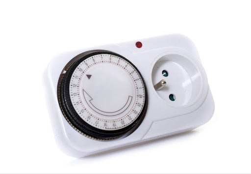
A timer switch is an electrical device designed to automatically turn a circuit ON or OFF after a preset time or at scheduled intervals. Unlike conventional electrical switches, it eliminates the need for constant manual control. A light switch timer, for example, can control lighting based on time, helping reduce energy consumption.
An electric timer switch works by using an internal timing mechanism, mechanical or electronic, to control electrical flow. In industrial settings, a timer switch for motor is widely used to manage start-delay, stop-delay, or cyclic operations. Timer switches are commonly installed in control panels, switchboards, and automation systems where accuracy and repeatability are essential. With proper wiring and setup, they become a reliable tool for time-based electrical control.
Working Principle of a Timer Switch
The working principle of a timer switch is based on controlling electrical circuits using time as a deciding factor. Once set, the timer activates or deactivates contacts automatically, reducing human intervention and improving operational consistency.
Time Setting Mechanism
The time-setting mechanism allows users to define delay duration or operating intervals. In an electric timer switch, this may involve dials, digital keys, or programmable settings. Once adjusted, the timer counts internally before triggering the switching action accurately.
Internal Switching Contacts
Inside the timer switch, electrical contacts open or close once the preset time is reached. These contacts behave similarly to electrical switches, but operate automatically. The contact configuration determines whether the load turns ON, OFF, or cycles.
Control Circuit Operation
A control circuit energizes the timing module and switching contacts. In a timer switch for motor, this circuit often interacts with contactors to safely control heavy loads without damaging the timer itself.
Power Supply and Reset
Most timer switches reset automatically after completing a cycle. Advanced models allow manual reset or repeat cycles, making them suitable for varied timer switch application requirements in automation systems.
Types of Timer Switches
There are different types of timers available, each designed for specific timing and control needs. Selecting the correct type ensures reliability and proper circuit performance.
On-Delay Timer
An on-delay timer waits before doing anything. Power comes in, the timer counts quietly, and only then does the output switch. This delay is helpful in motor circuits, where instant starts can strain shafts, belts, or bearings. Giving machines a short pause before running often reduces wear and avoids unnecessary stress during frequent restarts.
Off-Delay Timer
Off-delay timers don’t stop immediately. When power is removed, the output stays active for a short while. This small delay makes a big difference in everyday use. Lights don’t snap off instantly, and ventilation can continue briefly after shutdown. It feels smoother, safer, and more practical than abrupt switching.
Cyclic Timer
Cyclic timers are built for repetition. They switch a load ON, then OFF, over and over again, following a fixed rhythm. These timers are useful where constant attention isn’t possible. Fans, warning lights, or simple process controls benefit from this pattern, especially when regular pauses help prevent overheating or overuse.
Digital Programmable Timer
Digital programmable timers focus on flexibility. Instead of one fixed delay, they allow multiple schedules and easy changes. You don’t need to touch wiring to update settings. This makes them popular in buildings where timings change often- daily routines, seasonal adjustments, or equipment that doesn’t always follow the same operating pattern.
Timer Switch Diagram
A timer switch wiring diagram is basically a roadmap. It shows how power enters the timer, how control signals trigger it, and how the load is finally switched. When you understand the diagram properly, installation becomes safer and troubleshooting much easier. Most wiring issues don’t come from faulty timers. They come from misreading the diagram or missing one small connection detail.
Power Supply Terminals
The power supply terminals are where the timer gets its operating voltage. In a timer switch wiring diagram, these points are clearly labelled so there’s no confusion during installation. Connecting the wrong voltage here can damage the timer instantly, which is why installers usually double-check these terminals before energising the circuit.
Control Input Terminals
Control input terminals are used to start, stop, or reset the timing function. In a timer switch for motor, these inputs often receive signals from push buttons, limit switches, or sensors inside the control panel. They don’t carry load current but play a key role in deciding when the timer actually operates.
Output Contacts
Output contacts are the working end of the timer. These terminals connect directly to the load circuit or to a contactor. In drawings, the symbol of timer switch shows how these contacts change state after timing is complete, helping electricians understand exactly when power will be applied or removed.
Timer Symbol Representation
The symbol of timer switch follows standard electrical drawing conventions. It allows designers and technicians to instantly recognise timed control within a circuit. This distinction is important because timer symbols clearly separate automatic timing functions from regular electrical switches during planning, wiring, and fault diagnosis.
Also Read: How to Choose the Right Switch for Home: Power, Light, Modular & More Options
Applications of Timer Switch
Timer switches are used when something needs to run on time rather than on memory. Instead of relying on someone to switch things ON or OFF, the timing does the work. This is why these switches show up in homes, commercial spaces, and industrial setups alike. Once installed, they quietly handle routine control without needing constant attention.
Lighting Control
A light switch timer is commonly used in places where lights are easily forgotten. Garden lights, staircases, and parking areas are typical examples. The timer ensures lighting comes on when needed and switches off later on its own. This makes everyday use more convenient while keeping unnecessary power consumption in check.
Motor Control Systems
A timer switch for motor control helps manage how and when equipment starts and stops. Pumps, compressors, and conveyors often benefit from delayed or sequential operation. Instead of abrupt switching, timing allows machines to run more smoothly. Over time, this reduces mechanical stress and helps avoid unnecessary wear on motors.
Industrial Automation
In factory environments, timing plays a big role in keeping processes predictable. An electric timer switch is often used to control machine cycles or simple automation tasks. It keeps operations consistent, especially in repetitive work, and reduces dependence on manual switching that can lead to mistakes or uneven output.
Commercial Electrical Systems
Timer switches are widely used in commercial buildings for HVAC systems, signage, and scheduled equipment operation. These electrical switches help manage running hours more efficiently. Systems operate only when required, which cuts energy costs and keeps equipment from running longer than necessary.
Conclusion
A timer switch plays a vital role in modern electrical and automation systems by providing accurate, time-based control. From understanding different types of timers to reading a timer switch wiring diagram and identifying the symbol of timer switch, proper knowledge ensures correct selection and installation.
Whether used as a light switch timer in homes or a timer switch for motor in industries, timer switches improve efficiency, safety, and energy management. For reliable and high-quality timer switches and automation solutions, the eShop of Schneider Electric India offers a wide range of trusted products suitable for residential, commercial, and industrial applications.
FAQs
Q1. Why do timer switches stop working even when they’re new?
Ans. Most of the time, it’s not a manufacturing issue. Wrong wiring, incorrect voltage, or connecting a heavy load directly can damage a timer quickly. Heat trapped inside panels also shortens life. The timer usually gets blamed, but the setup is often the real problem.
Q2. Can I install a timer switch anywhere, or does location matter?
Ans. Location matters. A timer inside a dry panel lasts years. The same timer in a damp or dusty spot may fail early. If it’s outdoors or near moisture, enclosure protection becomes just as important as the timer itself.
Q3. Why does my timer switch lose settings sometimes?
Ans. This usually happens during power cuts. Basic timers reset when supply goes off. Digital models with backup memory handle this better. If outages are frequent, choosing a timer with memory support avoids constant reprogramming frustration.
Q4. Is it normal for a timer switch to make a clicking sound?
Ans. Yes, in many cases. The click is just the internal relay switching. It’s normal. If the sound becomes irregular or louder over time, that’s when it’s worth checking mounting, wiring, or load connection rather than assuming failure.
Q5. Can one timer control more than one device safely?
Ans. It can, as long as the load is handled correctly. Usually, the timer controls a relay or contactor instead of the devices directly. This setup is common and safe when designed properly, especially for grouped lighting or equipment control.


Comments