


Busduct Systems Explained: Meaning, Types & Power Distribution Uses
As electrical systems grow in size and complexity, traditional cable-based power distribution often becomes difficult to manage. Large current ratings demand multiple parallel cables, increased installation space, and higher maintenance effort. This is where a bus duct becomes a more structured and reliable alternative. Instead of routing bundles of cables, a single engineered system is used to transfer power safely and efficiently between major electrical equipment.
In modern infrastructure, an electrical bus duct is commonly used in power plants, industrial facilities, and commercial buildings where consistent performance and safety are critical. From transformers and generators to panels and low voltage switchgear, busducts simplify power distribution while improving system reliability. To understand their growing adoption, it is important to clearly understand what is bus duct, how a busduct system works, and how different classifications are used in real-world electrical installations.
What is a Busduct System?
To explain what is bus duct, it can be described as a prefabricated electrical system designed to transfer power between two or more electrical equipment using rigid conductors enclosed inside a metallic housing. In bus duct in electrical installations, these conductors are mounted on insulators to maintain electrical clearances and mechanical stability.
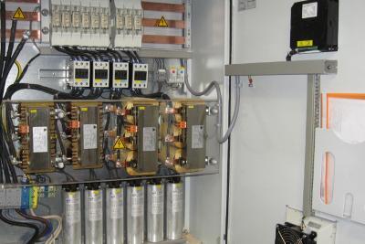
A busduct system consists of current-carrying conductors, insulating supports, and a non-magnetic enclosure that protects both the conductors and operating personnel. Compared to cables, a bus duct offers predictable impedance, improved heat dissipation, and higher short-circuit withstand capability. An electrical bus duct is selected based on current rating, voltage level, short-circuit requirement, available space, and environmental conditions.
With a properly engineered bus duct installation, systems become easier to inspect, expand, and maintain. This makes busducts particularly suitable for installations connected to transformers and low voltage switchgear, where reliability and long-term performance are essential.
Types of Busduct
As per the reference, air-insulated busducts are broadly classified based on phase segregation and voltage level. These bus duct types are selected according to fault level, application, and system design requirements.
MV Isolated Phase Busduct
MV Isolated Phase Busducts are primarily used in large power generation units. In this design, each phase conductor is housed in a separate metallic enclosure, eliminating the possibility of phase-to-phase faults. This configuration significantly reduces electromagnetic forces during short-circuit conditions.
In bus duct in electrical systems, isolated phase designs are commonly used to connect generator terminals to generator transformers, generator circuit breakers, and auxiliary transformers. This busduct system offers excellent shielding, high personnel safety, and reliable operation in adverse environmental conditions. It is chosen where high current capacity and fault containment are critical.
MV Segregated Phase Busduct
MV Segregated Phase Busducts house all phase conductors within a common enclosure, with internal metallic or insulated barriers separating each phase. These barriers reduce proximity effects and limit mechanical forces during phase-to-phase faults.
Among standard bus duct types, this design is widely used in medium-voltage applications such as connections between generators, transformers, and switchgear. A properly designed bus duct installation using segregated phase construction provides a balance between compact layout and fault performance, making it suitable for power plants and industrial substations.
LV Non-Segregated Phase Busduct
LV Non-Segregated Phase Busducts contain all phase conductors within a single enclosure without internal phase barriers. These systems are used exclusively in low-voltage applications. Two conductor arrangements are commonly adopted: conventional and interleaved.
Interleaved designs help balance impedance, reduce voltage drop, and lower short-circuit forces. This busduct system is widely used to interconnect transformers, PCCs, MCCs, and auxiliary transformers in industrial facilities. Among all bus duct types, this design is most common in low-voltage power distribution networks.
Sandwich Busduct
A sandwich bus duct is a compact design where conductors are closely spaced and separated by solid insulation. This results in a smaller overall cross-section, reduced impedance, and improved thermal performance.
The sandwich type bus duct is especially popular in commercial buildings, data centres, and high-rise installations. It integrates efficiently with low voltage switchgear and allows vertical and horizontal distribution with minimal space requirements. For projects requiring flexibility and aesthetic layout, sandwich designs are often preferred.
Applications of Busduct Systems
The structured design of a busduct system allows it to be applied across a wide range of industries. Compared to cable-based systems, bus duct installation offers better safety, cleaner layouts, and easier expansion.
Power Generation Plants
In power plants, an electrical bus duct is used to connect generators with transformers, excitation systems, and auxiliary equipment. These applications demand high current ratings and excellent short-circuit withstand capability. A bus duct provides stable mechanical performance and reliable power transfer under continuous operating conditions, making it ideal for generator applications.
Industrial Facilities
Manufacturing plants, steel mills, petrochemical facilities, and water treatment plants rely heavily on bus duct in electrical distribution systems. Busducts are used to connect transformers to PCCs, MCCs, and large motors. A well-designed busduct system reduces maintenance downtime and improves safety compared to multiple parallel cable runs.
Commercial Buildings
In commercial complexes such as malls, airports, hospitals, and data centres, LV busducts are widely used for structured power distribution. Although often referred to as sandwich construction, this refers to the physical design of the bus duct, not a separate type. These systems integrate efficiently with low voltage switchgear, allowing tap-off connections and future load expansion without major shutdowns.
Utilities and Infrastructure
Substations and infrastructure projects use different bus duct types depending on voltage level and fault requirements. A correctly engineered bus duct installation improves system reliability, reduces losses, and enhances operational safety in critical public utility networks.
Read Also: What’s The Use Of A Power Distribution Board and How Does It Work?
Why Busduct is Preferred Over Traditional Cables?
One of the main reasons a bus duct is preferred over cables is performance predictability. A busduct system offers controlled impedance, uniform current distribution, and superior short-circuit withstand capability. Heat dissipation is more efficient, and voltage drop is easier to manage compared to multiple parallel cables.
From an installation perspective, bus duct installation reduces congestion, improves accessibility, and simplifies inspection. Over the system’s lifetime, this results in lower maintenance effort and easier upgrades, especially in facilities with extensive low voltage switchgear networks.
Conclusion
Understanding what is bus duct and selecting the correct bus duct types is essential for designing safe, efficient, and scalable power distribution systems. Whether used in power plants, industrial facilities, or commercial buildings, a properly engineered busduct system offers long-term reliability and operational confidence.
With structured layouts, improved safety, and predictable performance, a bus duct has become a preferred alternative to traditional cabling in modern electrical infrastructure. For engineered solutions that meet global standards, the eShop of Schneider Electric offers a comprehensive range of busduct and low voltage switchgear solutions designed for demanding power distribution applications.
FAQs
Q1. Can a busduct be changed later if the layout of the plant changes?
Ans. In many cases, yes. Busducts aren’t poured into concrete forever. Sections can usually be added, removed, or shifted if space allows. Any change still needs checking for load limits and fault ratings before power goes back on.
Q2. Do busducts need earthing only at the ends or throughout the run?
Ans. They need continuous earthing. The enclosure is bonded section by section so there are no breaks. This isn’t optional. It’s what keeps touch voltage under control if something goes wrong inside the system.
Q3. Does heat around the busduct affect how much current it can carry?
Ans. Yes, more than people expect. A busduct running in a hot room won’t behave the same as one in open air. This is why ambient temperature is always part of the design, even if it looks fine on paper.
Q4. Do busduct systems need regular maintenance like cables do?
Ans. Not really in the same way. There’s no insulation to crack or sag. Most checks are visual like joints, discoloration, enclosure condition. If something is wrong, it usually shows signs early instead of failing suddenly.

Comments