 - AC-3 - <= 440 V 25 A - 110 V AC coil")


No sellers found for this product.
Excl. Tax
 Free Shipping

- 1. New modern look & feel of all machines
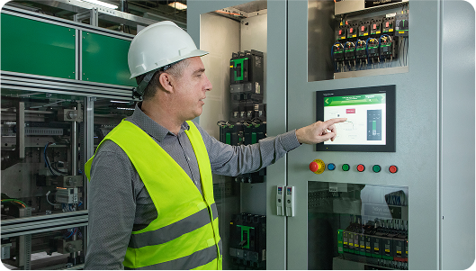
- 2. Designed to meet the requirements of industrial and HVAC applications
- 3. Easier to install and operate with multi-standard screws
- 4. With IEC60335-1 compliance, improved fire resistance, and dustproof auxiliaries
- 5. Digital customer experience for technical documents
- 6. Maintenance guide via EcoStruxureTM Facility Expect
TeSys D reversing contactor - 3P(3 NO) - AC-3 - <= 440 V 25 A - 110 V AC coil
- Description
- Specifications
- Environmental Data
- Documents
- Reviews
Description


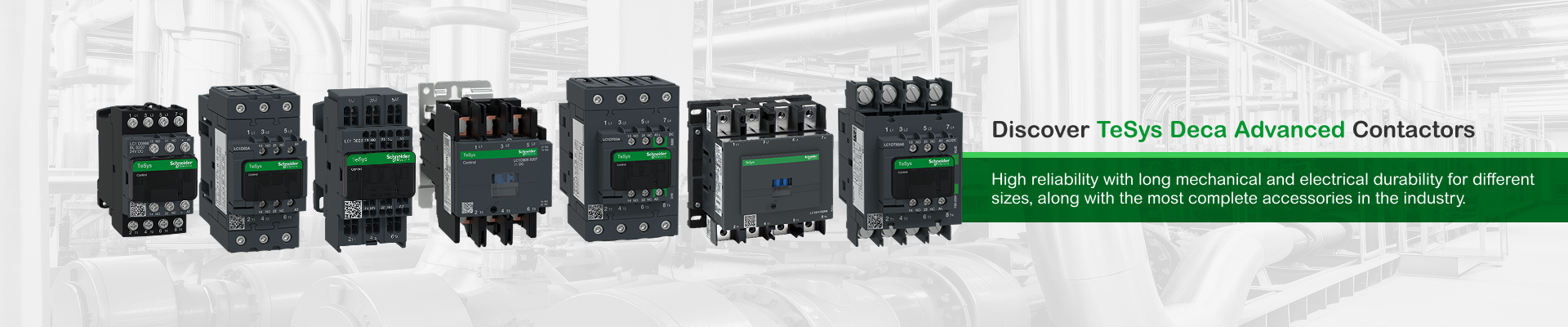
TeSys Deca Advanced Contactors
Stay smart with the world's best-selling motor control solutions from the inventor of the world's first contactor Schneider Electric. For almost a century, TeSys motor controls have driven the industry with innovations in motor protection, monitoring, and control.

Fewer Parts, More Power
TeSys Deca Advanced contactors simplify your maintenance services with 90% less references needed. Associated with TeSys Deca electronic overload relays, reduces heat generation and energy consumption by up to 50%.

Simple to install
TeSys Deca Advanced contactors offer quick simple setup, while maintaining a compact size and suitable for safety applications thanks to mechanically linked contacts and mirror contacts
Efficiency maintenance
High-performance solutions with up to 20 In breaking capacity, multistandard compliance, and direct PLC connectivity for seamless integration.

Enhance your power solutions with our extensive range of accessories
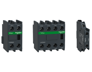
Auxiliary Contact Blocks
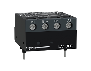
Interface module
Suppressor Module
Gain peace of mind, quality, and value for your installations
Versatile power for every application
TeSys Deca contactors have been designed for perfect integration into control systems. They can be used to create motor starters for almost any type of application. TeSys D contactors are available in 13 contactor ratings for inductive motor applications up to 150 full-load amps and resistive loads up to 200 amps. This IEC contactor can be mounted on DIN rail or mounted directly to a panel.


Cost and space saving
Lorem Ipsum is simply dummy text of the printing and

Reliable
Lorem Ipsum is simply dummy text of the printing and

Robust
Lorem Ipsum is simply dummy text of the printing and
Overview
| Activity | PPCTR |
|---|---|
| Range | TESYSTESYS DECA |
| Product name | TESYS DECATESYS DECA |
| Product or component type | REVERSING CONTACTOR |
| Device short name | LC2D |
| Contactor application | RESISTIVE LOADMOTOR CONTROL |
| Utilisation category | AC-1AC-3AC-3E |
| Device presentation | PREASSEMBLED WITH REVERSING POWER BUSBAR |
| Poles description | 3P |
| power pole contact composition | 3 NO |
| [Ue] rated operational voltage | POWER CIRCUIT: |
| [Ie] rated operational current | 25 A (AT |
| Motor power kW | 5.5 KW AT 220...230 V AC 50...60 HZ11 KW AT 380...400 V AC 50...60 HZ11 KW AT 415 V AC 50...60 HZ11 KW AT 440 V AC 50...60 HZ15 KW AT 500 V AC 50...60 HZ15 KW AT 660...690 V AC 50...60 HZ |
| motor power HP (UL / CSA) | 3 HP AT 230/240 V AC 60 HZ FOR 1 PHASE MOTORS5 HP AT 200/208 V AC 60 HZ FOR 3 PHASES MOTORS2 HP AT 115 V AC 60 HZ FOR 1 PHASE MOTORS7.5 HP AT 230/240 V AC 60 HZ FOR 3 PHASES MOTORS15 HP AT 460/480 V AC 60 HZ FOR 3 PHASES MOTORS20 HP AT 575/600 V AC 60 HZ FOR 3 PHASES MOTORS |
| Control circuit type | AC AT 50/60 HZ |
| [Uc] control circuit voltage | 110 V AC 50/60 HZ |
| Auxiliary contact composition | 1 NO + 1 NC |
| [Uimp] rated impulse withstand voltage | 6 KV CONFORMING TO IEC 60947 |
| Overvoltage category | III |
| [Ith] conventional free air thermal current | 10 A (AT 60 °C) FOR SIGNALLING CIRCUIT40 A (AT 60 °C) FOR POWER CIRCUIT |
| Irms rated making capacity | 140 A AC FOR SIGNALLING CIRCUIT CONFORMING TO IEC 60947-5-1250 A DC FOR SIGNALLING CIRCUIT CONFORMING TO IEC 60947-5-1450 A AT 440 V FOR POWER CIRCUIT CONFORMING TO IEC 60947 |
| Rated breaking capacity | 450 A AT 440 V FOR POWER CIRCUIT CONFORMING TO IEC 60947 |
| [Icw] rated short-time withstand current | 50 A 40 °C - 10 MIN FOR POWER CIRCUIT120 A 40 °C - 1 MIN FOR POWER CIRCUIT240 A 40 °C - 10 S FOR POWER CIRCUIT380 A 40 °C - 1 S FOR POWER CIRCUIT100 A - 1 S FOR SIGNALLING CIRCUIT120 A - 500 MS FOR SIGNALLING CIRCUIT140 A - 100 MS FOR SIGNALLING CIRCUIT |
| Associated fuse rating | 10 A GG FOR SIGNALLING CIRCUIT CONFORMING TO IEC 60947-5-163 A GG AT |
| Average impedance | 2 MOHM - ITH 40 A 50 HZ FOR POWER CIRCUIT |
| [Ui] rated insulation voltage | POWER CIRCUIT: 690 V CONFORMING TO IEC 60947-4-1POWER CIRCUIT: 600 V CSA CERTIFIEDPOWER CIRCUIT: 600 V UL CERTIFIEDSIGNALLING CIRCUIT: 690 V CONFORMING TO IEC 60947-1SIGNALLING CIRCUIT: 600 V CSA CERTIFIEDSIGNALLING CIRCUIT: 600 V UL CERTIFIED |
| Electrical durability | 1.65 MCYCLES 25 A AC-3 AT UE |
| Power dissipation per pole | 1.25 W AC-33.2 W AC-11.25 W AC-3E |
| Front cover | WITH |
| Interlocking type | MECHANICAL |
| Mounting support | RAILPLATE |
| Standards | CSA C22.2 NO 14EN 60947-4-1EN 60947-5-1IEC 60947-4-1IEC 60947-5-1UL 60335-2-40:ANNEX JJIEC 60335-1 |
| Product certifications | DNVCSACCCULGLLROS (Lloyds register of shipping)BVRINAGOSTUKCACB |
| Connections - terminals | CONTROL CIRCUIT: SCREW CLAMP TERMINALS 1 CABLE(S) 1…4 MM²FLEXIBLE WITHOUT CABLE ENDCONTROL CIRCUIT: SCREW CLAMP TERMINALS 2 CABLE(S) 1…4 MM²FLEXIBLE WITHOUT CABLE ENDCONTROL CIRCUIT: SCREW CLAMP TERMINALS 1 CABLE(S) 1…4 MM²FLEXIBLE WITH CABLE ENDCONTROL CIRCUIT: SCREW CLAMP TERMINALS 2 CABLE(S) 1…2.5 MM²FLEXIBLE WITH CABLE ENDCONTROL CIRCUIT: SCREW CLAMP TERMINALS 1 CABLE(S) 1…4 MM²SOLIDCONTROL CIRCUIT: SCREW CLAMP TERMINALS 2 CABLE(S) 1…4 MM²SOLIDPOWER CIRCUIT: SCREW CLAMP TERMINALS 1 CABLE(S) 2.5…10 MM²FLEXIBLE WITHOUT CABLE ENDPOWER CIRCUIT: SCREW CLAMP TERMINALS 2 CABLE(S) 2.5…10 MM²FLEXIBLE WITHOUT CABLE ENDPOWER CIRCUIT: SCREW CLAMP TERMINALS 1 CABLE(S) 1…10 MM²FLEXIBLE WITH CABLE ENDPOWER CIRCUIT: SCREW CLAMP TERMINALS 2 CABLE(S) 1.5…6 MM²FLEXIBLE WITH CABLE ENDPOWER CIRCUIT: SCREW CLAMP TERMINALS 1 CABLE(S) 1.5…10 MM²SOLIDPOWER CIRCUIT: SCREW CLAMP TERMINALS 2 CABLE(S) 2.5…10 MM²SOLID |
| Tightening torque | CONTROL CIRCUIT: 1.7 N.M - ON SCREW CLAMP TERMINALS - WITH SCREWDRIVER FLAT Ø 6 MMCONTROL CIRCUIT: 1.7 N.M - ON SCREW CLAMP TERMINALS - WITH SCREWDRIVER PHILIPS NO 2POWER CIRCUIT: 2.5 N.M - ON SCREW CLAMP TERMINALS - WITH SCREWDRIVER FLAT Ø 6 MMPOWER CIRCUIT: 2.5 N.M - ON SCREW CLAMP TERMINALS - WITH SCREWDRIVER PHILIPS NO 2CONTROL CIRCUIT: 1.7 N.M - ON SCREW CLAMP TERMINALS - WITH SCREWDRIVER POZIDRIV NO 2POWER CIRCUIT: 2.5 N.M - ON SCREW CLAMP TERMINALS - WITH SCREWDRIVER POZIDRIV NO 2 |
| Operating time | 12...22 MS CLOSING4...19 MS OPENING |
| Safety reliability level | B10D = 1369863 CYCLES CONTACTOR WITH NOMINAL LOAD CONFORMING TO EN/ISO 13849-1B10D = 20000000 CYCLES CONTACTOR WITH MECHANICAL LOAD CONFORMING TO EN/ISO 13849-1 |
| Mechanical durability | 15 MCYCLES |
| Maximum operating rate | 3600 CYC/H 60 °C |
| Coil technology | WITHOUT BUILT-IN SUPPRESSOR MODULE |
| Control circuit voltage limits | 0.3...0.6 UC (-40…70 °C):DROP-OUT AC 50/60 HZ0.8...1.1 UC (-40…60 °C):OPERATIONAL AC 50 HZ0.85...1.1 UC (-40…60 °C):OPERATIONAL AC 60 HZ1...1.1 UC (60…70 °C):OPERATIONAL AC 50/60 HZ |
| Inrush power in VA | 70 VA 60 HZ COS PHI 0.75 (AT 20 °C)70 VA 50 HZ COS PHI 0.75 (AT 20 °C) |
| Hold-in power consumption in VA | 7.5 VA 60 HZ COS PHI 0.3 (AT 20 °C)7 VA 50 HZ COS PHI 0.3 (AT 20 °C) |
| Heat dissipation | 2…3 W AT 50/60 HZ |
| Auxiliary contacts type | TYPE MECHANICALLY LINKED 1 NO + 1 NC CONFORMING TO IEC 60947-5-1 TYPE MIRROR CONTACT 1 NC CONFORMING TO IEC 60947-4-1 |
| Signalling circuit frequency | 25...400 HZ |
| Minimum switching current | 5 MA FOR SIGNALLING CIRCUIT |
| Minimum switching voltage | 17 V FOR SIGNALLING CIRCUIT |
| Non-overlap time | 1.5 MS ON DE-ENERGISATION BETWEEN NC AND NO CONTACT1.5 MS ON ENERGISATION BETWEEN NC AND NO CONTACT |
| Insulation resistance | > 10 MOHM FOR SIGNALLING CIRCUIT |
| IP degree of protection | IP20 FRONT FACE CONFORMING TO IEC 60529 |
| Climatic withstand | CONFORMING TO IACS E10 CONFORMING TO IEC 60947-1 ANNEX Q CATEGORY D |
| Protective treatment | TH CONFORMING TO IEC 60068-2-30 |
| Pollution degree | 3 |
| Ambient air temperature for operation | -40…60 °C60…70 °C WITH DERATING |
| Ambient air temperature for storage | -60…80 °C |
| Operating altitude | 0...3000 M |
| Fire resistance | 850 °C CONFORMING TO IEC 60695-2-1 |
| Flame retardance | V1 CONFORMING TO UL 94 |
| Mechanical robustness | VIBRATIONS CONTACTOR OPEN: 2 GN, 5...300 HZVIBRATIONS CONTACTOR CLOSED: 4 GN, 5...300 HZSHOCKS CONTACTOR CLOSED: 15 GN FOR 11 MSSHOCKS CONTACTOR OPEN: 8 GN FOR 11 MS |
| Height | 85 MM |
| Width | 90 MM |
| Depth | 92 MM |
| Net weight | 0.787 KG |
| Unit Type of Package 1 | PCE |
| Number of Units in Package 1 | 1 |
| Package 1 Height | 14.000 CM |
| Package 1 Width | 11.400 CM |
| Package 1 Length | 11.400 CM |
| Package 1 Weight | 940.000 G |
| Unit Type of Package 2 | S02 |
| Number of Units in Package 2 | 5 |
| Package 2 Height | 15.000 CM |
| Package 2 Width | 30.000 CM |
| Package 2 Length | 40.000 CM |
| Package 2 Weight | 5.107 KG |
| Warranty (in months) | 18 |
Environmental data
Schneider Electric aims to achieve Net Zero status by 2050 through supply chain partnerships, lower impact materials, and circularity via our ongoing "Use Better, Use Longer, Use Again" campaign to extend product lifetimes and recyclability.
| Sustainability | Green PremiumTM label is Schneider Electric’s commitment to delivering products with best-in-class environmental performance. Green Premium promises compliance with the latest regulations, transparency on environmental impacts, as well as circular and low-CO2 products. Guide to assessing product sustainability is a white paper that clarifies global eco-label standards and how to interpret environmental declarations. |
|---|---|
| Sustainable packaging | ✓ |
| Take-back | No |
| REACh free of SVHC | ✓ |
| RoHS exemption information | Yes (Download) |
| PVC free | Yes |
| REACh Regulation | REACh Declaration (Download) |
| EU RoHS Directive | EU RoHS Declaration (Download) |
| Environmental Disclosure | Product Environmental Profile (Download) |
| End of life manual availability | End of Life Information (Download) |
| Total lifecycle Carbon footprint | 254 kg CO2 eq. |
| Carbon footprint of the manufacturing phase [A1 to A3] | 4.837809627300629 |
| Carbon footprint of the manufacturing phase [A1 to A3] | 5 kg CO2 eq. |
| Carbon footprint of the distribution phase [A4] | 0.3652458529429971 |
| Carbon footprint of the distribution phase [A4] | 0.4 kg CO2 eq. |
| Carbon footprint of the use phase [B2, B3, B4, B6] | 246.842304725881 |
| Carbon footprint of the use phase [B2, B3, B4, B6] | 247 kg CO2 eq. |
| Carbon footprint of the end-of-life phase [C1 to C4] | 1.9114035758292245 |
| Carbon footprint of the end-of-life phase [C1 to C4] | 2 kg CO2 eq. |
| WEEE Label | The product must be disposed on European Union markets following specific waste collection and never end up in rubbish bins |
Reviews
Description
TeSys Deca Advanced Contactors
Stay smart with the world's best-selling motor control solutions from the inventor of the world's first contactor Schneider Electric. For almost a century, TeSys motor controls have driven the industry with innovations in motor protection, monitoring, and control.
Fewer Parts, More Power
TeSys Deca Advanced contactors simplify your maintenance services with 90% less references needed. Associated with TeSys Deca electronic overload relays, reduces heat generation and energy consumption by up to 50%.
Simple to install
TeSys Deca Advanced contactors offer quick simple setup, while maintaining a compact size and suitable for safety applications thanks to mechanically linked contacts and mirror contacts
Efficiency maintenance
High-performance solutions with up to 20 In breaking capacity, multistandard compliance, and direct PLC connectivity for seamless integration.
Enhance your power solutions with our extensive range of accessories
Auxiliary Contact Blocks
Interface module
Suppressor Module
Gain peace of mind, quality, and value for your installations
Versatile power for every application
TeSys Deca contactors have been designed for perfect integration into control systems. They can be used to create motor starters for almost any type of application. TeSys D contactors are available in 13 contactor ratings for inductive motor applications up to 150 full-load amps and resistive loads up to 200 amps. This IEC contactor can be mounted on DIN rail or mounted directly to a panel.
Cost and space saving
Lorem Ipsum is simply dummy text of the printing and
Reliable
Lorem Ipsum is simply dummy text of the printing and
Robust
Lorem Ipsum is simply dummy text of the printing and
Overview
| Activity | PPCTR |
|---|---|
| Range | TESYSTESYS DECA |
| Product name | TESYS DECATESYS DECA |
| Product or component type | REVERSING CONTACTOR |
| Device short name | LC2D |
| Contactor application | RESISTIVE LOADMOTOR CONTROL |
| Utilisation category | AC-1AC-3AC-3E |
| Device presentation | PREASSEMBLED WITH REVERSING POWER BUSBAR |
| Poles description | 3P |
| power pole contact composition | 3 NO |
| [Ue] rated operational voltage | POWER CIRCUIT: |
| [Ie] rated operational current | 25 A (AT |
| Motor power kW | 5.5 KW AT 220...230 V AC 50...60 HZ11 KW AT 380...400 V AC 50...60 HZ11 KW AT 415 V AC 50...60 HZ11 KW AT 440 V AC 50...60 HZ15 KW AT 500 V AC 50...60 HZ15 KW AT 660...690 V AC 50...60 HZ |
| motor power HP (UL / CSA) | 3 HP AT 230/240 V AC 60 HZ FOR 1 PHASE MOTORS5 HP AT 200/208 V AC 60 HZ FOR 3 PHASES MOTORS2 HP AT 115 V AC 60 HZ FOR 1 PHASE MOTORS7.5 HP AT 230/240 V AC 60 HZ FOR 3 PHASES MOTORS15 HP AT 460/480 V AC 60 HZ FOR 3 PHASES MOTORS20 HP AT 575/600 V AC 60 HZ FOR 3 PHASES MOTORS |
| Control circuit type | AC AT 50/60 HZ |
| [Uc] control circuit voltage | 110 V AC 50/60 HZ |
| Auxiliary contact composition | 1 NO + 1 NC |
| [Uimp] rated impulse withstand voltage | 6 KV CONFORMING TO IEC 60947 |
| Overvoltage category | III |
| [Ith] conventional free air thermal current | 10 A (AT 60 °C) FOR SIGNALLING CIRCUIT40 A (AT 60 °C) FOR POWER CIRCUIT |
| Irms rated making capacity | 140 A AC FOR SIGNALLING CIRCUIT CONFORMING TO IEC 60947-5-1250 A DC FOR SIGNALLING CIRCUIT CONFORMING TO IEC 60947-5-1450 A AT 440 V FOR POWER CIRCUIT CONFORMING TO IEC 60947 |
| Rated breaking capacity | 450 A AT 440 V FOR POWER CIRCUIT CONFORMING TO IEC 60947 |
| [Icw] rated short-time withstand current | 50 A 40 °C - 10 MIN FOR POWER CIRCUIT120 A 40 °C - 1 MIN FOR POWER CIRCUIT240 A 40 °C - 10 S FOR POWER CIRCUIT380 A 40 °C - 1 S FOR POWER CIRCUIT100 A - 1 S FOR SIGNALLING CIRCUIT120 A - 500 MS FOR SIGNALLING CIRCUIT140 A - 100 MS FOR SIGNALLING CIRCUIT |
| Associated fuse rating | 10 A GG FOR SIGNALLING CIRCUIT CONFORMING TO IEC 60947-5-163 A GG AT |
| Average impedance | 2 MOHM - ITH 40 A 50 HZ FOR POWER CIRCUIT |
| [Ui] rated insulation voltage | POWER CIRCUIT: 690 V CONFORMING TO IEC 60947-4-1POWER CIRCUIT: 600 V CSA CERTIFIEDPOWER CIRCUIT: 600 V UL CERTIFIEDSIGNALLING CIRCUIT: 690 V CONFORMING TO IEC 60947-1SIGNALLING CIRCUIT: 600 V CSA CERTIFIEDSIGNALLING CIRCUIT: 600 V UL CERTIFIED |
| Electrical durability | 1.65 MCYCLES 25 A AC-3 AT UE |
| Power dissipation per pole | 1.25 W AC-33.2 W AC-11.25 W AC-3E |
| Front cover | WITH |
| Interlocking type | MECHANICAL |
| Mounting support | RAILPLATE |
| Standards | CSA C22.2 NO 14EN 60947-4-1EN 60947-5-1IEC 60947-4-1IEC 60947-5-1UL 60335-2-40:ANNEX JJIEC 60335-1 |
| Product certifications | DNVCSACCCULGLLROS (Lloyds register of shipping)BVRINAGOSTUKCACB |
| Connections - terminals | CONTROL CIRCUIT: SCREW CLAMP TERMINALS 1 CABLE(S) 1…4 MM²FLEXIBLE WITHOUT CABLE ENDCONTROL CIRCUIT: SCREW CLAMP TERMINALS 2 CABLE(S) 1…4 MM²FLEXIBLE WITHOUT CABLE ENDCONTROL CIRCUIT: SCREW CLAMP TERMINALS 1 CABLE(S) 1…4 MM²FLEXIBLE WITH CABLE ENDCONTROL CIRCUIT: SCREW CLAMP TERMINALS 2 CABLE(S) 1…2.5 MM²FLEXIBLE WITH CABLE ENDCONTROL CIRCUIT: SCREW CLAMP TERMINALS 1 CABLE(S) 1…4 MM²SOLIDCONTROL CIRCUIT: SCREW CLAMP TERMINALS 2 CABLE(S) 1…4 MM²SOLIDPOWER CIRCUIT: SCREW CLAMP TERMINALS 1 CABLE(S) 2.5…10 MM²FLEXIBLE WITHOUT CABLE ENDPOWER CIRCUIT: SCREW CLAMP TERMINALS 2 CABLE(S) 2.5…10 MM²FLEXIBLE WITHOUT CABLE ENDPOWER CIRCUIT: SCREW CLAMP TERMINALS 1 CABLE(S) 1…10 MM²FLEXIBLE WITH CABLE ENDPOWER CIRCUIT: SCREW CLAMP TERMINALS 2 CABLE(S) 1.5…6 MM²FLEXIBLE WITH CABLE ENDPOWER CIRCUIT: SCREW CLAMP TERMINALS 1 CABLE(S) 1.5…10 MM²SOLIDPOWER CIRCUIT: SCREW CLAMP TERMINALS 2 CABLE(S) 2.5…10 MM²SOLID |
| Tightening torque | CONTROL CIRCUIT: 1.7 N.M - ON SCREW CLAMP TERMINALS - WITH SCREWDRIVER FLAT Ø 6 MMCONTROL CIRCUIT: 1.7 N.M - ON SCREW CLAMP TERMINALS - WITH SCREWDRIVER PHILIPS NO 2POWER CIRCUIT: 2.5 N.M - ON SCREW CLAMP TERMINALS - WITH SCREWDRIVER FLAT Ø 6 MMPOWER CIRCUIT: 2.5 N.M - ON SCREW CLAMP TERMINALS - WITH SCREWDRIVER PHILIPS NO 2CONTROL CIRCUIT: 1.7 N.M - ON SCREW CLAMP TERMINALS - WITH SCREWDRIVER POZIDRIV NO 2POWER CIRCUIT: 2.5 N.M - ON SCREW CLAMP TERMINALS - WITH SCREWDRIVER POZIDRIV NO 2 |
| Operating time | 12...22 MS CLOSING4...19 MS OPENING |
| Safety reliability level | B10D = 1369863 CYCLES CONTACTOR WITH NOMINAL LOAD CONFORMING TO EN/ISO 13849-1B10D = 20000000 CYCLES CONTACTOR WITH MECHANICAL LOAD CONFORMING TO EN/ISO 13849-1 |
| Mechanical durability | 15 MCYCLES |
| Maximum operating rate | 3600 CYC/H 60 °C |
| Coil technology | WITHOUT BUILT-IN SUPPRESSOR MODULE |
| Control circuit voltage limits | 0.3...0.6 UC (-40…70 °C):DROP-OUT AC 50/60 HZ0.8...1.1 UC (-40…60 °C):OPERATIONAL AC 50 HZ0.85...1.1 UC (-40…60 °C):OPERATIONAL AC 60 HZ1...1.1 UC (60…70 °C):OPERATIONAL AC 50/60 HZ |
| Inrush power in VA | 70 VA 60 HZ COS PHI 0.75 (AT 20 °C)70 VA 50 HZ COS PHI 0.75 (AT 20 °C) |
| Hold-in power consumption in VA | 7.5 VA 60 HZ COS PHI 0.3 (AT 20 °C)7 VA 50 HZ COS PHI 0.3 (AT 20 °C) |
| Heat dissipation | 2…3 W AT 50/60 HZ |
| Auxiliary contacts type | TYPE MECHANICALLY LINKED 1 NO + 1 NC CONFORMING TO IEC 60947-5-1 TYPE MIRROR CONTACT 1 NC CONFORMING TO IEC 60947-4-1 |
| Signalling circuit frequency | 25...400 HZ |
| Minimum switching current | 5 MA FOR SIGNALLING CIRCUIT |
| Minimum switching voltage | 17 V FOR SIGNALLING CIRCUIT |
| Non-overlap time | 1.5 MS ON DE-ENERGISATION BETWEEN NC AND NO CONTACT1.5 MS ON ENERGISATION BETWEEN NC AND NO CONTACT |
| Insulation resistance | > 10 MOHM FOR SIGNALLING CIRCUIT |
| IP degree of protection | IP20 FRONT FACE CONFORMING TO IEC 60529 |
| Climatic withstand | CONFORMING TO IACS E10 CONFORMING TO IEC 60947-1 ANNEX Q CATEGORY D |
| Protective treatment | TH CONFORMING TO IEC 60068-2-30 |
| Pollution degree | 3 |
| Ambient air temperature for operation | -40…60 °C60…70 °C WITH DERATING |
| Ambient air temperature for storage | -60…80 °C |
| Operating altitude | 0...3000 M |
| Fire resistance | 850 °C CONFORMING TO IEC 60695-2-1 |
| Flame retardance | V1 CONFORMING TO UL 94 |
| Mechanical robustness | VIBRATIONS CONTACTOR OPEN: 2 GN, 5...300 HZVIBRATIONS CONTACTOR CLOSED: 4 GN, 5...300 HZSHOCKS CONTACTOR CLOSED: 15 GN FOR 11 MSSHOCKS CONTACTOR OPEN: 8 GN FOR 11 MS |
| Height | 85 MM |
| Width | 90 MM |
| Depth | 92 MM |
| Net weight | 0.787 KG |
| Unit Type of Package 1 | PCE |
| Number of Units in Package 1 | 1 |
| Package 1 Height | 14.000 CM |
| Package 1 Width | 11.400 CM |
| Package 1 Length | 11.400 CM |
| Package 1 Weight | 940.000 G |
| Unit Type of Package 2 | S02 |
| Number of Units in Package 2 | 5 |
| Package 2 Height | 15.000 CM |
| Package 2 Width | 30.000 CM |
| Package 2 Length | 40.000 CM |
| Package 2 Weight | 5.107 KG |
| Warranty (in months) | 18 |
Environmental data
Schneider Electric aims to achieve Net Zero status by 2050 through supply chain partnerships, lower impact materials, and circularity via our ongoing "Use Better, Use Longer, Use Again" campaign to extend product lifetimes and recyclability.
| Sustainability | Green PremiumTM label is Schneider Electric’s commitment to delivering products with best-in-class environmental performance. Green Premium promises compliance with the latest regulations, transparency on environmental impacts, as well as circular and low-CO2 products. Guide to assessing product sustainability is a white paper that clarifies global eco-label standards and how to interpret environmental declarations. |
|---|---|
| Sustainable packaging | ✓ |
| Take-back | No |
| REACh free of SVHC | ✓ |
| RoHS exemption information | Yes (Download) |
| PVC free | Yes |
| REACh Regulation | REACh Declaration (Download) |
| EU RoHS Directive | EU RoHS Declaration (Download) |
| Environmental Disclosure | Product Environmental Profile (Download) |
| End of life manual availability | End of Life Information (Download) |
| Total lifecycle Carbon footprint | 254 kg CO2 eq. |
| Carbon footprint of the manufacturing phase [A1 to A3] | 4.837809627300629 |
| Carbon footprint of the manufacturing phase [A1 to A3] | 5 kg CO2 eq. |
| Carbon footprint of the distribution phase [A4] | 0.3652458529429971 |
| Carbon footprint of the distribution phase [A4] | 0.4 kg CO2 eq. |
| Carbon footprint of the use phase [B2, B3, B4, B6] | 246.842304725881 |
| Carbon footprint of the use phase [B2, B3, B4, B6] | 247 kg CO2 eq. |
| Carbon footprint of the end-of-life phase [C1 to C4] | 1.9114035758292245 |
| Carbon footprint of the end-of-life phase [C1 to C4] | 2 kg CO2 eq. |
| WEEE Label | The product must be disposed on European Union markets following specific waste collection and never end up in rubbish bins |