 - AC-3 - <= 440 V 50 A - 220 V AC 50/60 Hz coil")


No sellers found for this product.
Incl. Tax
 Free Shipping

TeSys D contactor - 3P(3 NO) - AC-3 - <= 440 V 50 A - 220 V AC 50/60 Hz coil
- Description
- Specifications
- Documents
- Reviews
Description


TeSys Deca Advanced Contactors
Stay smart with the world's best-selling motor control solutions from the inventor of the world's first contactor Schneider Electric. For almost a century, TeSys motor controls have driven the industry with innovations in motor protection, monitoring, and control.

Fewer Parts, More Power
TeSys Deca Advanced contactors simplify your maintenance services with 90% less references needed. Associated with TeSys Deca electronic overload relays, reduces heat generation and energy consumption by up to 50%.

Simple to install
TeSys Deca Advanced contactors offer quick simple setup, while maintaining a compact size and suitable for safety applications thanks to mechanically linked contacts and mirror contacts

Efficiency maintenance
High-performance solutions with up to 20 In breaking capacity, multistandard compliance, and direct PLC connectivity for seamless integration.


Enhance your power solutions with our extensive range of accessories
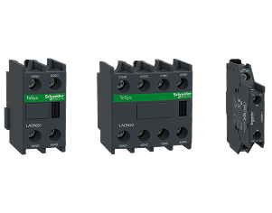
Auxiliary Contact Blocks
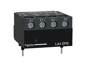
Interface module
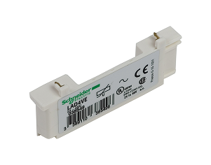
Suppressor Module
Gain peace of mind, quality, and value for your installations
Versatile power for every application
TeSys Deca contactors have been designed for perfect integration into control systems. They can be used to create motor starters for almost any type of application. TeSys D contactors are available in 13 contactor ratings for inductive motor applications up to 150 full-load amps and resistive loads up to 200 amps. This IEC contactor can be mounted on DIN rail or mounted directly to a panel.


Cost and space saving
Lorem Ipsum is simply dummy text of the printing and

Reliable
Lorem Ipsum is simply dummy text of the printing and

Robust
Lorem Ipsum is simply dummy text of the printing and
Overview
| Weight (in Kg) | 0.916 |
|---|---|
| Net weight | 0.855 kg |
| auxiliary contacts type | type mechanically linked 1 NO + 1 NC conforming to IEC 60947-5-1 type mirror contact 1 NC conforming to IEC 60947-4-1 |
| Pole Contact Composition | 3 NO |
| Product Or Component Type | contactor |
| Mechanical Durability | 6 Mcycles |
| Protective Treatment | TH conforming to IEC 60068-2-30 |
| Insulation Resistance | > 10 MOhm for signalling circuit |
| Minimum Switching Current | 5 mA for signalling circuit |
| Minimum Switching Voltage | 17 V for signalling circuit |
| Poles Description | 3P |
| Average Impedance | 1.5 mOhm - Ith 80 A 50 Hz for power circuit |
| Auxiliary Contact Composition | 1 NO + 1 NC |
| Contact Compatibility | M2 |
| Contactor Application | resistive load motor control |
| Motor Starter Type | direct on-line contactor |
| Protective Cover | with |
| Signalling Circuit Frequency | 25...400 Hz |
| [IP] Degree of Protection | IP20 front face conforming to IEC 60529 |
| Connections Terminals | control circuit: screw clamp terminals 2 cable(s) 1-2.5 mm²flexible with cable end control circuit: screw clamp terminals 1 cable(s) 1-4 mm²flexible without cable end control circuit: screw clamp terminals 2 cable(s) 1-4 mm²flexible without cable end control circuit: screw clamp terminals 1 cable(s) 1-4 mm²flexible with cable end control circuit: screw clamp terminals 1 cable(s) 1-4 mm²solid without cable end control circuit: screw clamp terminals 2 cable(s) 1-4 mm²solid without cable end power circuit: EverLink BTR screw connectors 1 cable(s) 1-35 mm²flexible without cable end power circuit: EverLink BTR screw connectors 2 cable(s) 1-25 mm²flexible without cable end power circuit: EverLink BTR screw connectors 1 cable(s) 1-35 mm²flexible with cable end power circuit: EverLink BTR screw connectors 2 cable(s) 1-25 mm²flexible with cable end power circuit: EverLink BTR screw connectors 1 cable(s) 1-35 mm²solid without cable end power circuit: EverLink BTR screw connectors 2 cable(s) 1-25 mm²solid without cable end |
| [Uimp] Rated Impulse Wthstand Voltage | 6 kV conforming to IEC 60947 |
| Irms Rated Making Capacity | 140 A AC for signalling circuit conforming to IEC 60947-5-1 250 A DC for signalling circuit conforming to IEC 60947-5-1 900 A at 440 V for power circuit conforming to IEC 60947 |
| power_range | 7-11 kW at 200-240 V 3 phases 15-25 kW at 380-440 V 3 phases 15-25 kW at 200-240 V 3 phases 30-50 kW at 380-440 V 3 phases 30-50 kW at 480-500 V 3 phases |
| Ambient air temperature for operation | -40-60 °C 60-70 °C with derating |
| Range of Product | TeSys D TeSys Deca |
| Tightening Torque | control circuit: 1.7 N.m - on EverLink BTR screw connectors - with screwdriver flat Ø 6 mm control circuit: 1.7 N.m - on EverLink BTR screw connectors - with screwdriver Philips No 2 power circuit: 8 N.m - on EverLink BTR screw connectors - cable 25-35 mm² hexagonal screw head 4 mm power circuit: 5 N.m - on EverLink BTR screw connectors - cable 1-25 mm² hexagonal screw head 4 mm control circuit: 1.7 N.m - on EverLink BTR screw connectors - with screwdriver pozidriv No 2 power circuit: 2.5 N.m - on EverLink BTR screw connectors - with screwdriver pozidriv No 2 - on EverLink BTR screw connectors |
| Standards | CSA C22.2 No 14 EN 60947-4-1 EN 60947-5-1 IEC 60947-4-1 IEC 60947-5-1 UL 508 IEC 60335-1 |
| Product Certifications | RINA DNV CSA GOST BV GL UL CCC LROS (Lloyds register of shipping) |
| Mechanical Robustness | vibrations contactor open: 2 Gn, 5...300 Hz vibrations contactor closed: 4 Gn, 5...300 Hz shocks contactor closed: 15 Gn for 11 ms shocks contactor open: 10 Gn for 11 ms |
| [Ith] Conventional Free Air Thermal Current | 10 A (at 60 °C) for signalling circuit 80 A (at 60 °C) for power circuit |
| [ui] Rated Insulation Voltage | power circuit: 600 V CSA certified power circuit: 600 V UL certified signalling circuit: 690 V conforming to IEC 60947-1 signalling circuit: 600 V CSA certified signalling circuit: 600 V UL certified power circuit: 690 V conforming to IEC 60947-4-1 |
| Associated Fuse Rating | 10 A gG for signalling circuit conforming to IEC 60947-5-1 100 A gG at <= 690 V coordination type 1 for power circuit 100 A gG at <= 690 V coordination type 2 for power circuit |
| Mounting support | plate rail |
| Control Circuit Type | AC at 50/60 Hz |
| Control Circuit Voltage Limits | 0.3...0.6 Uc (-40-70 °C):drop-out AC 50/60 Hz 0.8...1.1 Uc (-40-60 °C):operational AC 50 Hz 0.85...1.1 Uc (-40-60 °C):operational AC 60 Hz 1...1.1 Uc (60-70 °C):operational AC 50/60 Hz |
| Electrical Durability | 1.45 Mcycles 50 A AC-3 at Ue <= 440 V 1.1 Mcycles 80 A AC-1 at Ue <= 440 V 1.45 Mcycles 50 A AC-3e at Ue <= 440 V |
| Fire Resistance | 850 °C conforming to IEC 60695-2-1 |
| Heat Dissipation | 4-5 W at 50/60 Hz |
| Hold-In Power Consumption In VA | 13-13 VA 60 Hz cos phi 0.3 (at 20 °C) 15-15 VA 50 Hz cos phi 0.3 (at 20 °C) |
| Inrush Power In VA | 140-140 VA 60 Hz cos phi 0.75 (at 20 °C) 160-160 VA 50 Hz cos phi 0.75 (at 20 °C) |
| Maximum Operating Rate | 3600 cyc/h 60 °C |
| Motor Power Kw | 15 kW at 220...230 V AC 50/60 Hz (AC-3) 22 kW at 380...400 V AC 50/60 Hz (AC-3) 30 kW at 500 V AC 50/60 Hz (AC-3) 33 kW at 660...690 V AC 50/60 Hz (AC-3) 25 kW at 415 V AC 50/60 Hz (AC-3) 30 kW at 440 V AC 50/60 Hz (AC-3) 11 kW at 400 V AC 50/60 Hz (AC-4) 15 kW at 220...230 V AC 50/60 Hz (AC-3e) 22 kW at 380...400 V AC 50/60 Hz (AC-3e) 30 kW at 500 V AC 50/60 Hz (AC-3e) 33 kW at 660...690 V AC 50/60 Hz (AC-3e) 25 kW at 415 V AC 50/60 Hz (AC-3e) 30 kW at 440 V AC 50/60 Hz (AC-3e) |
| Operating Time | 4...19 ms opening 12...26 ms closing |
| Power Dissipation Per Pole | 3.7 W AC-3 9.6 W AC-1 3.7 W AC-3e |
| Rated Breaking Capacity | 900 A at 440 V for power circuit conforming to IEC 60947 |
| [Icw] rated short-time withstand current | 400 A 40 °C - 10 s for power circuit 810 A 40 °C - 1 s for power circuit 84 A 40 °C - 10 min for power circuit 208 A 40 °C - 1 min for power circuit 100 A - 1 s for signalling circuit 120 A - 500 ms for signalling circuit 140 A - 100 ms for signalling circuit |
| Flame Retardance | V1 conforming to UL 94 |
| Contactor Coil Voltage | 220 V AC standard |
| Safety Reliability Level | B10d = 1369863 cycles contactor with nominal load conforming to EN/ISO 13849-1 B10d = 20000000 cycles contactor with mechanical load conforming to EN/ISO 13849-1 |
| Climatic Withstand | conforming to IACS E10 conforming to IEC 60947-1 Annex Q category D |
| Coil Technology | without built-in suppressor module |
| Motor Power Hp | 3 hp at 115 V AC 50/60 Hz for 1 phase motors 7.5 hp at 230/240 V AC 50/60 Hz for 1 phase motors 15 hp at 200/208 V AC 50/60 Hz for 3 phases motors 15 hp at 230/240 V AC 50/60 Hz for 3 phases motors 40 hp at 460/480 V AC 50/60 Hz for 3 phases motors 40 hp at 575/600 V AC 50/60 Hz for 3 phases motors |
| Device short name | LC1D |
| Depth | 120 mm |
| Ambient air temperature for storage | -60-80 °C |
| Height | 122 mm |
| Overvoltage Category | III |
| width | 55 mm |
| Pollution degree | 3 |
| Utilisation category | AC-4 AC-1 AC-3 AC-3e |
| Operating altitude | 0...3000 m |
| Non-Overlap Time | 1.5 ms on de-energisation between NC and NO contact 1.5 ms on energisation between NC and NO contact |
| Compatibility code | LC1D |
| [Uc] Control Circuit Voltage | 220 V AC 50/60 Hz |
| [Ue] Rated Operational Voltage | power circuit: <= 690 V AC 25...400 Hz power circuit: <= 300 V DC |
| Brand | Schneider Electric |
| Height | 6.2 |
| Length | 15.2 |
| Width | 13.5 |
Documents
Reviews
Description
TeSys Deca Advanced Contactors
Stay smart with the world's best-selling motor control solutions from the inventor of the world's first contactor Schneider Electric. For almost a century, TeSys motor controls have driven the industry with innovations in motor protection, monitoring, and control.
Fewer Parts, More Power
TeSys Deca Advanced contactors simplify your maintenance services with 90% less references needed. Associated with TeSys Deca electronic overload relays, reduces heat generation and energy consumption by up to 50%.
Simple to install
TeSys Deca Advanced contactors offer quick simple setup, while maintaining a compact size and suitable for safety applications thanks to mechanically linked contacts and mirror contacts
Efficiency maintenance
High-performance solutions with up to 20 In breaking capacity, multistandard compliance, and direct PLC connectivity for seamless integration.
Enhance your power solutions with our extensive range of accessories
Auxiliary Contact Blocks
Interface module
Suppressor Module
Gain peace of mind, quality, and value for your installations
Versatile power for every application
TeSys Deca contactors have been designed for perfect integration into control systems. They can be used to create motor starters for almost any type of application. TeSys D contactors are available in 13 contactor ratings for inductive motor applications up to 150 full-load amps and resistive loads up to 200 amps. This IEC contactor can be mounted on DIN rail or mounted directly to a panel.
Cost and space saving
Lorem Ipsum is simply dummy text of the printing and
Reliable
Lorem Ipsum is simply dummy text of the printing and
Robust
Lorem Ipsum is simply dummy text of the printing and
Overview
| Weight (in Kg) | 0.916 |
|---|---|
| Net weight | 0.855 kg |
| auxiliary contacts type | type mechanically linked 1 NO + 1 NC conforming to IEC 60947-5-1 type mirror contact 1 NC conforming to IEC 60947-4-1 |
| Pole Contact Composition | 3 NO |
| Product Or Component Type | contactor |
| Mechanical Durability | 6 Mcycles |
| Protective Treatment | TH conforming to IEC 60068-2-30 |
| Insulation Resistance | > 10 MOhm for signalling circuit |
| Minimum Switching Current | 5 mA for signalling circuit |
| Minimum Switching Voltage | 17 V for signalling circuit |
| Poles Description | 3P |
| Average Impedance | 1.5 mOhm - Ith 80 A 50 Hz for power circuit |
| Auxiliary Contact Composition | 1 NO + 1 NC |
| Contact Compatibility | M2 |
| Contactor Application | resistive load motor control |
| Motor Starter Type | direct on-line contactor |
| Protective Cover | with |
| Signalling Circuit Frequency | 25...400 Hz |
| [IP] Degree of Protection | IP20 front face conforming to IEC 60529 |
| Connections Terminals | control circuit: screw clamp terminals 2 cable(s) 1-2.5 mm²flexible with cable end control circuit: screw clamp terminals 1 cable(s) 1-4 mm²flexible without cable end control circuit: screw clamp terminals 2 cable(s) 1-4 mm²flexible without cable end control circuit: screw clamp terminals 1 cable(s) 1-4 mm²flexible with cable end control circuit: screw clamp terminals 1 cable(s) 1-4 mm²solid without cable end control circuit: screw clamp terminals 2 cable(s) 1-4 mm²solid without cable end power circuit: EverLink BTR screw connectors 1 cable(s) 1-35 mm²flexible without cable end power circuit: EverLink BTR screw connectors 2 cable(s) 1-25 mm²flexible without cable end power circuit: EverLink BTR screw connectors 1 cable(s) 1-35 mm²flexible with cable end power circuit: EverLink BTR screw connectors 2 cable(s) 1-25 mm²flexible with cable end power circuit: EverLink BTR screw connectors 1 cable(s) 1-35 mm²solid without cable end power circuit: EverLink BTR screw connectors 2 cable(s) 1-25 mm²solid without cable end |
| [Uimp] Rated Impulse Wthstand Voltage | 6 kV conforming to IEC 60947 |
| Irms Rated Making Capacity | 140 A AC for signalling circuit conforming to IEC 60947-5-1 250 A DC for signalling circuit conforming to IEC 60947-5-1 900 A at 440 V for power circuit conforming to IEC 60947 |
| power_range | 7-11 kW at 200-240 V 3 phases 15-25 kW at 380-440 V 3 phases 15-25 kW at 200-240 V 3 phases 30-50 kW at 380-440 V 3 phases 30-50 kW at 480-500 V 3 phases |
| Ambient air temperature for operation | -40-60 °C 60-70 °C with derating |
| Range of Product | TeSys D TeSys Deca |
| Tightening Torque | control circuit: 1.7 N.m - on EverLink BTR screw connectors - with screwdriver flat Ø 6 mm control circuit: 1.7 N.m - on EverLink BTR screw connectors - with screwdriver Philips No 2 power circuit: 8 N.m - on EverLink BTR screw connectors - cable 25-35 mm² hexagonal screw head 4 mm power circuit: 5 N.m - on EverLink BTR screw connectors - cable 1-25 mm² hexagonal screw head 4 mm control circuit: 1.7 N.m - on EverLink BTR screw connectors - with screwdriver pozidriv No 2 power circuit: 2.5 N.m - on EverLink BTR screw connectors - with screwdriver pozidriv No 2 - on EverLink BTR screw connectors |
| Standards | CSA C22.2 No 14 EN 60947-4-1 EN 60947-5-1 IEC 60947-4-1 IEC 60947-5-1 UL 508 IEC 60335-1 |
| Product Certifications | RINA DNV CSA GOST BV GL UL CCC LROS (Lloyds register of shipping) |
| Mechanical Robustness | vibrations contactor open: 2 Gn, 5...300 Hz vibrations contactor closed: 4 Gn, 5...300 Hz shocks contactor closed: 15 Gn for 11 ms shocks contactor open: 10 Gn for 11 ms |
| [Ith] Conventional Free Air Thermal Current | 10 A (at 60 °C) for signalling circuit 80 A (at 60 °C) for power circuit |
| [ui] Rated Insulation Voltage | power circuit: 600 V CSA certified power circuit: 600 V UL certified signalling circuit: 690 V conforming to IEC 60947-1 signalling circuit: 600 V CSA certified signalling circuit: 600 V UL certified power circuit: 690 V conforming to IEC 60947-4-1 |
| Associated Fuse Rating | 10 A gG for signalling circuit conforming to IEC 60947-5-1 100 A gG at <= 690 V coordination type 1 for power circuit 100 A gG at <= 690 V coordination type 2 for power circuit |
| Mounting support | plate rail |
| Control Circuit Type | AC at 50/60 Hz |
| Control Circuit Voltage Limits | 0.3...0.6 Uc (-40-70 °C):drop-out AC 50/60 Hz 0.8...1.1 Uc (-40-60 °C):operational AC 50 Hz 0.85...1.1 Uc (-40-60 °C):operational AC 60 Hz 1...1.1 Uc (60-70 °C):operational AC 50/60 Hz |
| Electrical Durability | 1.45 Mcycles 50 A AC-3 at Ue <= 440 V 1.1 Mcycles 80 A AC-1 at Ue <= 440 V 1.45 Mcycles 50 A AC-3e at Ue <= 440 V |
| Fire Resistance | 850 °C conforming to IEC 60695-2-1 |
| Heat Dissipation | 4-5 W at 50/60 Hz |
| Hold-In Power Consumption In VA | 13-13 VA 60 Hz cos phi 0.3 (at 20 °C) 15-15 VA 50 Hz cos phi 0.3 (at 20 °C) |
| Inrush Power In VA | 140-140 VA 60 Hz cos phi 0.75 (at 20 °C) 160-160 VA 50 Hz cos phi 0.75 (at 20 °C) |
| Maximum Operating Rate | 3600 cyc/h 60 °C |
| Motor Power Kw | 15 kW at 220...230 V AC 50/60 Hz (AC-3) 22 kW at 380...400 V AC 50/60 Hz (AC-3) 30 kW at 500 V AC 50/60 Hz (AC-3) 33 kW at 660...690 V AC 50/60 Hz (AC-3) 25 kW at 415 V AC 50/60 Hz (AC-3) 30 kW at 440 V AC 50/60 Hz (AC-3) 11 kW at 400 V AC 50/60 Hz (AC-4) 15 kW at 220...230 V AC 50/60 Hz (AC-3e) 22 kW at 380...400 V AC 50/60 Hz (AC-3e) 30 kW at 500 V AC 50/60 Hz (AC-3e) 33 kW at 660...690 V AC 50/60 Hz (AC-3e) 25 kW at 415 V AC 50/60 Hz (AC-3e) 30 kW at 440 V AC 50/60 Hz (AC-3e) |
| Operating Time | 4...19 ms opening 12...26 ms closing |
| Power Dissipation Per Pole | 3.7 W AC-3 9.6 W AC-1 3.7 W AC-3e |
| Rated Breaking Capacity | 900 A at 440 V for power circuit conforming to IEC 60947 |
| [Icw] rated short-time withstand current | 400 A 40 °C - 10 s for power circuit 810 A 40 °C - 1 s for power circuit 84 A 40 °C - 10 min for power circuit 208 A 40 °C - 1 min for power circuit 100 A - 1 s for signalling circuit 120 A - 500 ms for signalling circuit 140 A - 100 ms for signalling circuit |
| Flame Retardance | V1 conforming to UL 94 |
| Contactor Coil Voltage | 220 V AC standard |
| Safety Reliability Level | B10d = 1369863 cycles contactor with nominal load conforming to EN/ISO 13849-1 B10d = 20000000 cycles contactor with mechanical load conforming to EN/ISO 13849-1 |
| Climatic Withstand | conforming to IACS E10 conforming to IEC 60947-1 Annex Q category D |
| Coil Technology | without built-in suppressor module |
| Motor Power Hp | 3 hp at 115 V AC 50/60 Hz for 1 phase motors 7.5 hp at 230/240 V AC 50/60 Hz for 1 phase motors 15 hp at 200/208 V AC 50/60 Hz for 3 phases motors 15 hp at 230/240 V AC 50/60 Hz for 3 phases motors 40 hp at 460/480 V AC 50/60 Hz for 3 phases motors 40 hp at 575/600 V AC 50/60 Hz for 3 phases motors |
| Device short name | LC1D |
| Depth | 120 mm |
| Ambient air temperature for storage | -60-80 °C |
| Height | 122 mm |
| Overvoltage Category | III |
| width | 55 mm |
| Pollution degree | 3 |
| Utilisation category | AC-4 AC-1 AC-3 AC-3e |
| Operating altitude | 0...3000 m |
| Non-Overlap Time | 1.5 ms on de-energisation between NC and NO contact 1.5 ms on energisation between NC and NO contact |
| Compatibility code | LC1D |
| [Uc] Control Circuit Voltage | 220 V AC 50/60 Hz |
| [Ue] Rated Operational Voltage | power circuit: <= 690 V AC 25...400 Hz power circuit: <= 300 V DC |
| Brand | Schneider Electric |
| Height | 6.2 |
| Length | 15.2 |
| Width | 13.5 |