
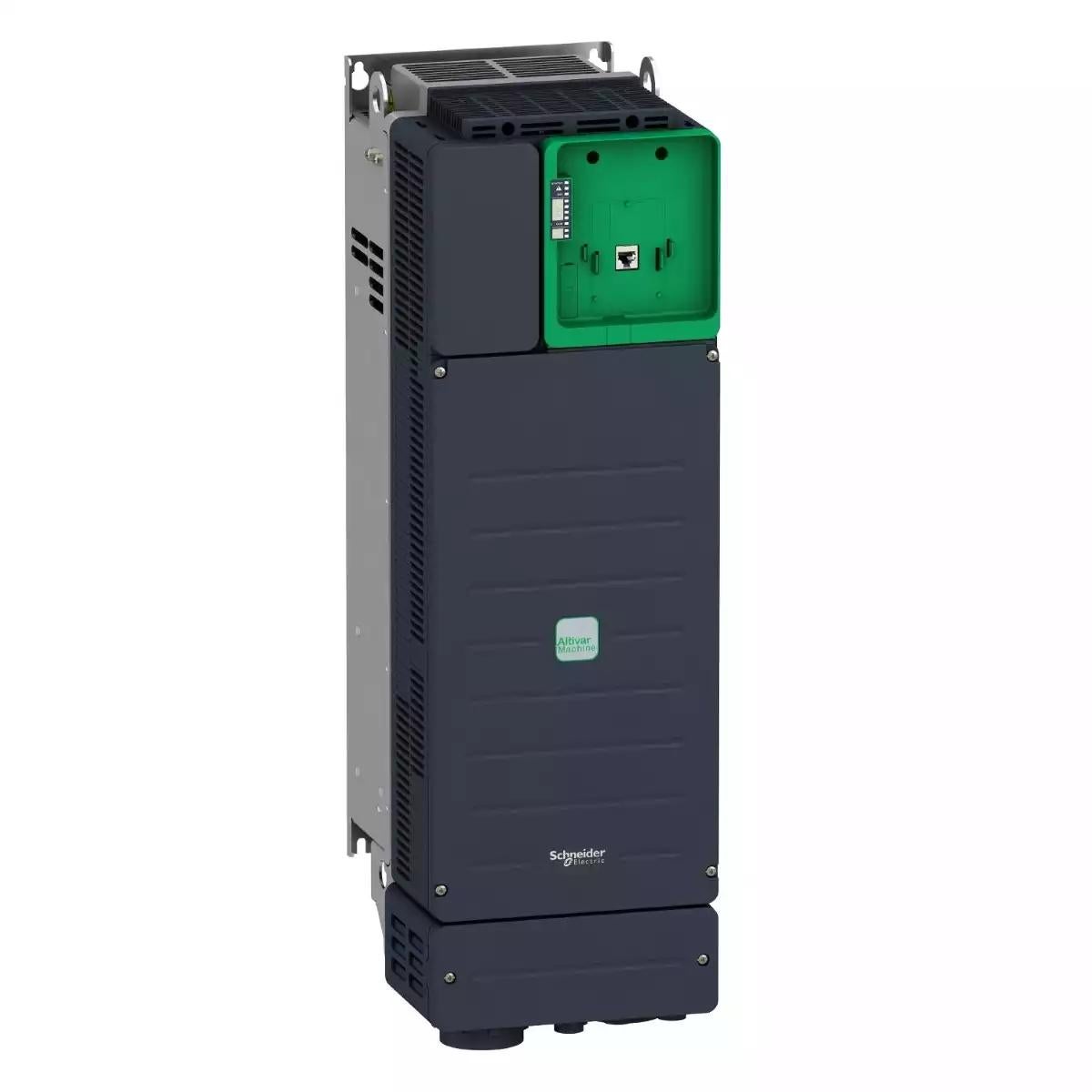
Altivar 340 variable speed drive - 37kW- 400V - 3 phases - ATV340 Ethernet
Incl. Tax
All Sellers
| Seller | Price | Delivery | Shipping Cost | |
|---|---|---|---|---|
|
View Seller Profile
B2B Network
|
|
Shipping Cost
Free Shipping
|
No sellers found for this product.
Description
This Altivar 340 variable speed drive can feed 3-phase synchronous and asynchronous motors in open and closed loop control. Altivar Machine ATV340 drives are sized heavy duty as standard. It works at a rated power up to 37kW / 50hp and a rated voltage from 380V to 480V AC. ATV340 has been designed to meet the needs of applications for harsh environments, such as vibration, shock and non-conductive dust and where high temperature resistance up to 60 °C is needed. This product integrates Modbus serial line communication protocols as standard. This drive features multi-protocol Ethernet embedded, it consists of Ethernet IP and Modbus TCP communication interfaces. it weighs 28.4kg and its dimensions are, 213mm wide, 660mm high, 262mm deep. ATV340 incorporates functions and features suitable for the most common applications, including packaging, material handling, material working, hoisting. It conforms to international standards IEC/EN 61800-5-1 and IEC/EN 61800-3 (immunity and conducted and radiated EMC emissions), IEC 60721-3, IEC 61508, IEC 13849-1. It is also CE, UL, CSA, and TÜV certified. Accessories and options (encoder interface modules, I/O expansion modules, communication modules, braking resistors, line chokes, additional EMC filters) are available with Altivar Machine ATV340 drives, depending on the drive rating. It is designed to be mounted in vertical position (+/- 10 °) on a panel, thanks to 4 fixing holes. It is fully integrated inside Schneider Electric’s EcoStruxure Machine through DTM. It is possible to configure, control, and diagnose ATV340 drives directly in SoMachine and SoMove software by means of the same software brick (DTM). It is eco-friendly and complies with directives such as RoHS relating to environmental protection.
Product Details
| Weight (in Kg) | 37.6 |
|---|---|
| Net weight | 28.4 kg |
| Operating Position | vertical +/- 10 degree |
| Connector Type | connector(s)1 x RJ45, Modbus serial on front face connector(s)1 x RJ45, Modbus serial for HMI on front face connector(s)2 x RJ45, Ethernet IP/Modbus TCP on front face 3 RJ45 |
| Output Voltage | <= power supply voltage |
| [Us] rated supply voltage | 380...480 V 380...480 V - 15...10 % |
| Product Or Component Type | variable speed drive |
| Ambient air temperature for operation | -15-60 °C -15-50 °C without derating (vertical position) 50-60 °C with derating factor (vertical position) |
| Mounting Mode | wall mount |
| Nema Degree of Protection | NEMA 1 |
| Continuous Output Current | 88 A at 4 kHz for normal duty 74.5 A at 4 kHz for heavy duty |
| Housing Material | plastic |
| Insulation Resistance | > 1 MOhm 500 V DC for 1 minute to earth |
| Minimum Switching Current | relay output R1B: 5 mA at 24 V DC relay output R2C: 5 mA at 24 V DC |
| Supply Frequency | 50...60 Hz +/- 5 % |
| Safety Function | STO (safe torque off) SIL 3 |
| Assembly Style | with heat sink |
| Noise Level | 63.5 dB |
| Network frequency | 50...60 Hz |
| Type of Cooling | forced convection |
| Ambient Air Transport Temperature | -40-70 °C |
| Analogue Input Number | 3 |
| Analogue Output Number | 2 |
| Exchange Mode | half duplex, full duplex, autonegotiation Ethernet IP/Modbus TCP |
| Motor Starter Type | variable speed drive |
| Degree of Protection | UL type 1 |
| Refresh Time | relay output (R1, R2, R3): 5 ms (+/- 0.5 ms) |
| Communication Port Protocol | Modbus TCP Modbus serial EtherNet/IP |
| Accuracy | #ERROR! |
| Maximum Output Frequency | 0.599 kHz |
| Regulation Loop | adjustable PID regulator |
| 4 Quadrant Operation Possible | TRUE |
| Apparent Power | 57.4 kVA at 480 V (normal duty) 49.1 kVA at 480 V (heavy duty) |
| Application in Domestic and Commercial Area Permitted | FALSE |
| Application in Industrial Area Permitted | TRUE |
| Base Load Current at High Overload | 74.5 A |
| Base Load Current at Low Overload | 88.0 A |
| Brake Chopper Integrated | TRUE |
| Braking to Standstill | by DC injection |
| Capacity of Dc Link | 3000.0 µF |
| Computer Port | TRUE |
| Data Format | 8 bits, configurable odd, even or no parity |
| Design of Frequency Changer | U converter |
| Emc Filter | class C3 EMC filter integrated |
| Emc Limit Value (complied) | TRUE |
| Encoder Protocol | 1 Vpp EnDat 2.2 resolver RS 422 SSI 24V SSI 5V TTL/HTL |
| Environmental Class (during Operation) | class 3C3 according to IEC 60721-3-3 class 3S3 according to IEC 60721-3-3 |
| Environmental Class (during Storage) | class 1C3 according to EN 60721-3-1 class 1S2 according to EN 60721-3-1 |
| Environmental Class (during Transport) | class 2C3 according to EN 60721-3-2 class 2S1 according to EN 60721-3-2 |
| Input Compatibility | STOA, STOB: discrete input level 1 PLC conforming to EN/IEC 61131-2 DI1...DI8: discrete input level 1 PLC conforming to EN/IEC 61131-2 DI7, DI8: pulse input level 1 PLC conforming to IEC 65A-68 |
| Isolation | between power and control terminals |
| Line Current | 79.8 A at 380 V (normal duty) 69.1 A at 480 V (normal duty) 67.1 A at 380 V (heavy duty) 59.0 A at 480 V (heavy duty) 79.8 A at 380 V with internal line choke (normal duty) 69.1 A at 480 V with internal line choke (normal duty) 67.1 A at 380 V with internal line choke (heavy duty) 59 A at 480 V with internal line choke (heavy duty) 67.1 A 59.0 A |
| Linearity Error | AI1, AI2, AI3: +/- 0.15 % of maximum value for analog input AQ1, AQ2: +/- 0.2 % for analog output |
| Maximum Acceleration Under Shock Impact (during Operation) | 150 m/s² at 11 ms |
| Maximum Acceleration Under Shock Load (during Storage) | 150 m/s² at 11 ms |
| Maximum Acceleration Under Vibratory Load (during Storage) | 10 m/s² at 13...200 Hz |
| Maximum Acceleration Under Vibratory Load (during Transport) | 10 m/s² at 13...200 Hz |
| Maximum Associated Fuse Rating | 125.0 A |
| Maximum Deflection Under Vibratory Load (during Operation) | 1.5 mm at 2...13 Hz |
| Maximum Deflection Under Vibratory Load (during Storage) | 1.5 mm at 2...13 Hz |
| Maximum Deflection Under Vibratory Load (during Transport) | 1.5 mm at 2...13 Hz |
| Maximum input current | 79.8 A |
| Maximum Output Voltage | 480 V |
| Maximum Thdi | <48 % full load conforming to IEC 61000-3-12 <48 % 80 % load conforming to IEC 61000-3-12 |
| Method of Access | slave Modbus RTU slave Modbus TCP |
| Nominal Output Power | 37.0 kW |
| Nominal Switching Frequency | 4 kHz |
| Number of Addresses | 1-247 |
| Number of Hw Interfaces Industrial Ethernet | 2 |
| Number of Hw Interfaces Serial Rs485 | 1 |
| Number of Input Phases | 3 |
| Number of Output Phases | 3 |
| Operating Element Present | TRUE |
| Optical Interface Present | FALSE |
| Option Card | communication module, PROFINET communication module, DeviceNet communication module, CANopen communication module, EtherCAT |
| Permitted Relative Humidity (during Operation) | class 3K5 according to EN 60721-3 |
| Permitted Relative Humidity (during Storage) | class 1K5 according to EN 60721-3 |
| Permitted Relative Humidity (during Transport) | class 2K5 according to EN 60721-3 |
| Physical Interface | 2-wire RS 485 |
| Power Loss Per Device Current Dependent | 903.0 W |
| Power Loss Static Current Independent | 33.0 W |
| Prospective Line Isc | 50 kA |
| Relative Symmetric Mains Voltage Tolerance | 10 % |
| Relative Symmetric Network Frequency Tolerance | 5 % |
| Relay Output Number | 3 |
| Specific Application | machine |
| Speed Drive Output Frequency | 0.1-599 Hz |
| Supporting Protocol for Asi | FALSE |
| Supporting Protocol for Bacnet | FALSE |
| Supporting Protocol for Can | FALSE |
| Supporting Protocol for Devicenet | FALSE |
| Supporting Protocol for Devicenet Safety | FALSE |
| Supporting Protocol for Ethernet/ip | TRUE |
| Supporting Protocol for Foundation Fieldbus | FALSE |
| Supporting Protocol for Interbus | FALSE |
| Supporting Protocol for Knx | FALSE |
| Supporting Protocol for Lon | FALSE |
| Supporting Protocol for Modbus | TRUE |
| Supporting Protocol for Other Bus Systems | FALSE |
| Supporting Protocol for Profibus | FALSE |
| Supporting Protocol for Profinet Cba | FALSE |
| Supporting Protocol for Profinet Io | FALSE |
| Supporting Protocol for Profisafe | FALSE |
| Supporting Protocol for Safetybus p | FALSE |
| Supporting Protocol for Sercos | FALSE |
| Supporting Protocol for Suconet | FALSE |
| Supporting Protocol for Tcp/ip | TRUE |
| Synchronous Motor Control Profile | reluctance motor permanent magnet motor |
| Type of Polarization | no impedance |
| Variant | standard version |
| Volume of Cooling Air | 240.0 m3/h |
| With Safety Function Safe Brake Management (sbc/sbt) | TRUE |
| With Safety Function Safe Direction (sdi) | FALSE |
| With Safety Function Safe Operating Stop (sos) | FALSE |
| With Safety Function Safe Position (sp) | FALSE |
| With Safety Function Safe Programmable Logic | FALSE |
| With Safety Function Safe Speed Monitor (ssm) | FALSE |
| With Safety Function Safe Stop 1 (ss1) | TRUE |
| With Safety Function Safe Torque Off (sto) | TRUE |
| With Safety Function Safely Limited Position (slp) | FALSE |
| With Safety Function Safely Limited Speed (sls) | TRUE |
| With Sft Fct Safe Stop 2 (ss2) | FALSE |
| Supporting Protocol for As-interface Safety at Work | FALSE |
| Supporting Protocol for Data-highway | FALSE |
| Supporting Protocol for Interbus-safety | FALSE |
| Maximum Acceleration Under Vibrational Stress (during Operation) | 10 m/s² at 13...200 Hz |
| Nominal Output Current | 74.5 A |
| Switching Frequency | 2...16 kHz adjustable 4...16 kHz with derating factor |
| Product Certifications | UL CSA TÃœV EAC CTick |
| Electromagnetic Compatibility | electrostatic discharge immunity test level 3 conforming to IEC 61000-4-2 radiated radio-frequency electromagnetic field immunity test level 3 conforming to IEC 61000-4-3 electrical fast transient/burst immunity test level 4 conforming to IEC 61000-4-4 1.2/50 µs - 8/20 µs surge immunity test level 3 conforming to IEC 61000-4-5 conducted radio-frequency immunity test level 3 conforming to IEC 61000-4-6 |
| IP degree of protection | IP20 |
| Protection Type | thermal protection: motor safe torque off: motor motor phase loss: motor thermal protection: drive safe torque off: drive overheating: drive overcurrent: drive output overcurrent between motor phase and earth: drive output overcurrent between motor phases: drive short-circuit between motor phase and earth: drive short-circuit between motor phases: drive motor phase loss: drive DC Bus overvoltage: drive line supply overvoltage: drive line supply undervoltage: drive input supply loss: drive exceeding limit speed: drive break on the control circuit: drive |
| Standards | EN/IEC 61800-3 EN/IEC 61800-5-1 IEC 60721-3 IEC 61508 IEC 13849-1 UL 618000-5-1 UL 508C IEC 61000-3-12 |
| Motor Power Hp | 60 hp for normal duty 50 hp for heavy duty |
| Operating altitude | <= 4800 m with current derating above 1000m |
| Power Dissipation in w | natural convection: 90 W at 380 V, switching frequency 4 kHz (heavy duty) forced convection: 796 W at 380 V, switching frequency 4 kHz (heavy duty) natural convection: 105 W at 380 V, switching frequency 4 kHz (normal duty) forced convection: 943 W at 380 V, switching frequency 4 kHz (normal duty) |
| Vibration Resistance | 1.5 mm peak to peak (f= 2-13 Hz) conforming to IEC 60068-2-6 1 gn (f= 13-200 Hz) conforming to IEC 60068-2-6 |
| Product Specific Application | machine |
| Transmission Rate | 4.8 kbit/s 9.6 kbit/s 19.2 kbit/s 38.4 kbit/s |
| 1 Phase Low Current Possible | FALSE |
| Acceleration and Deceleration Ramps | linear adjustable separately from 0.01...9999 s S, U or customized |
| Asynchronous Motor Control Profile | optimized torque mode variable torque standard constant torque standard |
| Maximum Transient Current | 105.6 A during 60 s (normal duty) 105.6 A during 2 s (normal duty) 111.8 A during 60 s (heavy duty) 111.8 A during 2 s (heavy duty) |
| Motor Slip Compensation | adjustable can be suppressed automatic whatever the load not available in permanent magnet motor law |
| Sampling Duration | 2 ms +/- 0.5 ms (DI1...DI8) - discrete input 5 ms +/- 1 ms (DI7, DI8) - pulse input 1 ms +/- 1 ms (AI1, AI2, AI3) - analog input 5 ms +/- 1 ms (AQ1, AQ2) - analog output |
| Electrical Connection | screw terminal, clamping capacity: 0.75...1.5 mm² for control screw terminal, clamping capacity: 35...50 mm² for line side screw terminal, clamping capacity: 35...50 mm² for DC bus screw terminal, clamping capacity: 50 mm² for motor control: screw terminal 0.75...1.5 mm²/AWG 18...AWG 16 line side: screw terminal 35...50 mm²/AWG 2...AWG 1 DC bus: screw terminal 35...50 mm²/AWG 3...AWG 1 motor: screw terminal 50 mm²/AWG 1 |
| Analogue Input Type | AI1 software-configurable current: 0...20 mA, impedance: 250 Ohm, resolution 12 bits AI1 software-configurable temperature probe or water level sensor AI1 software-configurable voltage: 0...10 V DC, impedance: 31.5 kOhm, resolution 12 bits AI2 software-configurable voltage: - 10...10 V DC, impedance: 31.5 kOhm, resolution 12 bits |
| Analogue Output Type | software-configurable voltage AQ1, AQ2: 0...10 V DC impedance 470 Ohm, resolution 10 bits software-configurable current AQ1, AQ2: 0...20 mA impedance 500 Ohm, resolution 10 bits |
| Discrete Input Logic | positive logic (source) (STOA, STOB), < 5 V (state 0), > 11 V (state 1) positive logic (source) (DI1...DI8), < 5 V (state 0), > 11 V (state 1) negative logic (sink) (DI1...DI8), > 16 V (state 0), < 10 V (state 1) positive logic (source) (DI7, DI8), < 0.6 V (state 0), > 2.5 V (state 1) 16 preset speeds |
| Relay Output Type | relay outputs R1A relay outputs R1C electrical durability 100000 cycles relay outputs R2A relay outputs R2C electrical durability 100000 cycles |
| Discrete Output Type | programmable output DQ1, DQ2 30 V DC 100 mA |
| Maximum Switching Current | relay output R1C on resistive load, cos phi = 1 : 3 A at 250 V AC relay output R1C on resistive load, cos phi = 1 : 3 A at 30 V DC relay output R1C on inductive load, cos phi = 0.4 and L/R = 7 ms: 2 A at 250 V AC relay output R1C on inductive load, cos phi = 0.4 and L/R = 7 ms: 2 A at 30 V DC relay output R2C on resistive load, cos phi = 1 : 5 A at 250 V AC relay output R2C on resistive load, cos phi = 1 : 5 A at 30 V DC relay output R2C on inductive load, cos phi = 0.4 and L/R = 7 ms: 2 A at 250 V AC relay output R2C on inductive load, cos phi = 0.4 and L/R = 7 ms: 2 A at 30 V DC |
| Depth | 262.0 mm |
| Marking | CE |
| Overvoltage Category | class III |
| Height | 660.0 mm |
| Ambient air temperature for storage | -40-70 °C |
| Range of Product | Altivar Machine ATV340 |
| Shock Resistance | 15 gn for 11 ms conforming to IEC 60068-2-27 |
| width | 213.0 mm |
| Pollution degree | 2 2 conforming to EN/IEC 61800-5-1 |
| Discrete Input Number | 8 |
| Motor Power Kw | 45 kW for normal duty 37 kW for heavy duty |
| Discrete Output Number | 1 |
| Transmission Frame | RTU |
| Maximum Acceleration Under Shock Load (during Transport) | 150 m/s² at 11 ms |
| Network Number Of Phases | 3 phases |
| Discrete Input Type | PTI safe torque off: 0-30 kHz, 24 V DC (30 V) DI1...DI5 programmable as pulse input, 24 V DC (30 V), impedance: 3.5 kOhm programmable |
| Power Range | 30-50 kW at 380-440 V 3 phases 30-50 kW at 480-500 V 3 phases |
| input/output type | logic output DQ-: 0-1 kHz, <= 30 V DC, 100 mA logic output DQ+: 0-1 kHz, <= 30 V DC, 100 mA programmable as pulse output DQ+: 0-30 kHz, <= 30 V DC, 20 mA |
| Brand | Schneider Electric |
| Height | 56 |
| Length | 84 |
| Width | 34 |